From the Stevens Indicator By Stevens Institute of Technology, Volume XI, 1894:
Richard H. Rice is the Treasurer of the newly incorporated Rice & Sargent Engine Company of Providence R.I., which has been organized to build the Rice & Sargent Engine. This engine is described as a “four valve automatic cut-off engine having rotary Corliss valves, double-ported, provided with trip gear, and especially designed for electric and cable plants, mills, and other work requiring an engine fitted for heavy and continuous service and close regulation of speed.”
After graduating Mr. Rice was a draughtsman with the Bath Iron Works for one year; and for three years was Chief Draughtsman for E.D. Levitt, for whom he designed some very ponderous engineering work. For the past four years he has been the Mechanical Engineer and Superintendant of the William A. Harris Steam Engine Company, of Providence.
Mr. John W. Sargent, the Secretary of the new company, has had extensive experience the William Cramp & Son’s Ship and Engine Building Company in Philadelphia, E.D. Levitt, and the Dickson Manufacturing Company.
The President, Mr. R.A. Robertson, and the Vice President Mr. Z. Chafee are respectively Treasurer and President of the Builders Iron Foundry, of Providence.
From Transactions of the American Society of Mechanical Engineers, Volume 44, 1922
Who’s who in New England: A Biographical Dictionary of Contemporaries, 1909
Richard Henry Rice was born on January 9, 1863 in Rockland, ME, and died on February 10, 1922 in Boltion NY. He received an M.E degree from Stevens Institute in Hoboken, NJ in 1885. In 1885 he was in charge of the testing laboratory at the Stevens Institute. From 1885-1886 he was a Special Apprentice at the Pittsburgh, Cincinnati, Chicago & St. Louis Railway shops in Dennision, OH. From 1886-1887 he was a designer of marine engines at the Bath Iron Works, Bath ME. He was married to Mary Susan Durgin of Concord, NH on April 6, 1887. They had three children; Phyllis, Richard Drury, and Susan Durgin. From 1887-1891 they lived in Cambridge, MA where he was the a designer and chief draughtsman for E.D. Levitt, Cambridgeport, MA. From 1891-1894 they lived in Providence, RI where he was Superintendant Engineer at the William A. Harris Steam Engine Company, Providence, RI. Mary Susan (Durgin) Rice died in 1891. From 1894-1903 he was Treasurer of the Rice & Sargent Engine Company and Providence Engineering Works of Providence R.I. Richard married Allice Woodman Kimball on 3/26/1898. Starting in 1903 he was a consultant on steam engineering and in charge of turbine development at the General Electric Company in Lynn, MA. He received an honorary PhD in Engineering from the Stevens Institute in 1921.
There is a Rice and Sargent on display at the Erie Canal Park.
Patents:
318,037 Mechanism for operating Slide-Valves, May 19, 1895.
473,085 Cut-Off Valve Gear, April 19, 1892
485,432 Steam Engine, November 1, 1892.
485,433 Steam Engine Valve Gear, November 1, 1892.
516,633 Eccentric for Operating Valves of a Steam Engine, March 13, 1894.
516,634 Valve-Gear, March 13, 1894.
526,267 Valve Gear, September 18, 1894.
539,758 Stop-Motion for Governors May 21, 1895
536,156 Stop-Motion for Governors, May 19, 1895
545,414 Exhaust Valve, August 27, 1895.
563,862 Stop-Motion for Governors, July 14, 1896
571,687 Cylindrical Rotary Valve, November 17, 1896
590,554 Construction of Balance Wheels, September 21, 1897.
642,054 Steam-Actuated Dash-Pot for Engines, January 23, 1900.
760,808 Engine Governor, May 24, 1904.
737,495 Valve-Gear for Steam Engines, August 25, 1903.
989,062 Stop-Motion for Steam-Engines and other Prime Movers, April 11, 1911.
1,020,225 Engine Governor, March 12, 1912.
CA 131,835 Stop Motion for Steam Engines, March 21, 1911.
CA 147,975 Steam Engine Mechanism, May 13, 1913.
From Valves and Valve Gears, Page 119 with lots of help from Google
RICE AND SARGENT CORLISS ENGINE
247. A Corliss engine with a number of distinctive features is manufactured by the Providence Engineering Works, probably the oldest engine-building shops in America now engaged in the same business. The engine, however, is one of the most recently designed of all the well-known makes of the Corliss type, being the joint work of Mr. Richard H. Rice and Mr. John W. Sargent, in 1893. It is designed for heavy duty work and for speeds a little higher than those usually obtained with the Corliss engine. It is adapted for use in direct-connected electrical work or with belt or rope drive.

A perspective view of a single-cylinder Rice and Sargent engine is shown in Fig. 157. The several parts are as follows:
S, Steam admission pipe. B, Belt to governor shaft.
C, Engine cylinder. G, Governor case.
R, Crank case. O, O1, Governor rods.
E, Eccentric case. T, Live-steam eccentric rod.
T1 T2, Clutch rod and reach rod for live-steam valves.
X1,X2, Clutch rod and reach rod for exhaust valves.
X, Exhaust eccentric rod. A, Dashpot rod.
N Dashpot cover.
248. It will be noted that the wristplate, which is a common and characteristic feature of Corliss engines generally, is not used. This engine was the first, so far as known, to be built without a wristplate. Two eccentrics, one for live steam and the other for exhaust, are used on engines of all sizes, thus permitting of a wide range of cut-off. Two distinctive forms of governors are used by the Company, one a special form of the Rites inertia governor developed by the Providence Engineering Works, and the other a purely centrifugal governor designed at the same works and known as the Sargent governor. The latter is the newer form and is being now generally used on this engine. The structural features of the valve gear are such as to permit speeds up to 200 revolutions per minute in the smaller sizes of engines. The larger engines run up to 150 r. p. m.
249. The live-steam and exhaust-steam valves of the Rice and Sargent engine are shown in section, together with the valve chambers and the head-end half of the engine cylinder in Fig. 158. The live-steam valve, 1, is double-ported, and so is the exhaust valve 8, although they are quite different in construction. In larger sizes of engines triple-ported live-steam and exhaust valves are used to further diminish the valve movement. The live steam enters at 2, and the exhaust steam passes out at 7. The piston is shown at 4, the cylinder head at 9, and the cylinder-head cover at 10.

250. The valve gear immediately surrounding the crank-end steam-valve stem at V in Fig. 157 is shown in detail, and also in its two extreme positions, in Figs. 159 and 160. In Fig. 159 the valve is just beginning its motion under the influence of the live-steam eccentric and, after it has traveled a distance equal to its lap, will open the ports. In Fig. 160 the ports are wide open and the valve is just starting its quick return motion under the influence of the dashpot.

The several parts of the mechanism are:
1, Valve stem.
2, Governor rocker turning freely on bearing on bonnet, and carrying roll pins 8 and 10.
3, Governing rod leading to head-end valve, 01 in Fig. 157.
4, Full arc of swing of governor rocker.
5, Rod from governor, 0 in Fig. 157.
6, Valve-stem “lever” or rocker keyed to valve stem and carrying pin 7 to which dashpot rod 11 is attached and carrying also pin 13 to which the latch block 14 is pivoted.
17, “Steam” rocker which turns freely on the valve stem and to which are pivoted the clutch rod 16 (T1 in Fig. 157), the reach rod 18 (T2 in Fig. 157), and the toe block 19, which is integral with the cam lever or cam arm 9.
Action of the Rice and Sargent Valve Gear
251. The action of the gear is as follows: The eccentric pulls the rocker 17, Fig. 159, to the right and this carries the toe 19, which in turn pushes the latch 14 and the valve stem rocker 6, thus rotating the valve and lifting the dashpot piston. This continues until the curve 12, Fig. 160, of the cam lever comes into contact with the rollers 8 and 10 on the governor arm which is stationary for any one cut-off, and then the arm 9 and the toe 19 are rotated downwards about the center 20 just enough to permit the toe to disengage from the latch 14, when the valve-stem rocker 6 is quickly rotated clockwise, Fig. 159, by the action of the dashpot. The latch 14 is prevented from dropping lower than the position shown by a stop block. As the toe 19 is carried back by the steam rocker 17, it slightly lifts the end of the latch, which then swings a small amount about the pin 13. The latch, however, drops back in place by gravity as soon as the toe passes.
252. For earlier cut-off the governor rod 5 moves to the right, thus carrying the pins 8 and 10 to the left and permitting the cam-lever curves 12 to stroke them sooner and so disengage the toe and clutch earlier. The part of the cam arm to the right of 12 is a curve such as will guide the working corner of the toe plate 19 so that it moves in an arc of a circle about 1 as a center, thus insuring contact with the latch 14 up to the time that the knock-off curve 12 comes into action on the rollers.
When the governor rod 5 is in its extreme right-hand position the pins 8 and 10 are so far to the left that only the part of the cam lever to the left of the curve 12 comes into contact with them at any point in the valve-gear travel, and this part is so designed that it does not allow the toe 19 to rise high enough to engage the latch block 14 and consequently the valve is not moved and no steam is admitted at all until the engine slows down.
253. The cam arrangement here described is just the reverse of the ordinary Corliss arrangement. In this case, the swinging arm 9 carries the cam curve, and the governor rocker 2 carries the rollers, whereas on the usual forms of construction the governor rocker carries the cam surface and the “toe arm” carries the roller or slide bar. The present arrangement allows the toe and cam to be operated by gravity only, whereas a leaf or other form of spring is necessary to cause the toe to engage with the latch in most of the usual forms of construction.
254. The valve gear surrounding the exhaust valve stem is shown in detail in Fig. 161, and in its proper position at U in Fig. 157. The exhaust clutch rod X1 is indicated at 1 in Fig. 161. It swings the bell crank 3 through the angle 2 about the center 5. The pin at 5 is set in a bracket 6 which is a part of the exhaust bonnet casting. A connecting link 7 joins the end of the bell-crank arm with the arm 10 which is keyed to the valve stem. The purpose of this connecting link, and its proportions, are such that it will give the exhaust valve considerable motion at the time of opening the ports and a very small motion when the exhaust port is closed and the live steam is pressing the valve down on its cylindrical seat. The large travel during opening is represented approximately by the angle 8, while the small angle traveled during closure is represented approximately by the angle 9. The latter angle, it will be observed, is small because the centers of the bell-crank arm, the connecting link, and the crank pin are in line, or nearly so, when the arm 10 is in its extreme right-hand position, and there is always slight travel of a follower as the driving mechanism reaches a dead point, and there is no motion at all at the dead point.

Rites Governor as Applied to Rice and Sargent Engine
255. The governor is shown at G in Fig. 157. The governor weights are driven by the governor shaft J through the belt B from the main shaft of the engine. In Fig. 162 the governor casing is shown at 7 and also at 7 in the section taken on X X. The governor shaft at 1 has attached to it two arms 2, 2, which carry pins supporting freely the weights 4 and 20. The weight 4 carries a balancing curved rib 5, and also has attached to it a complete circular U-shaped ring as shown at 6 in the full front view, and also at 6 in the section on X X. The weight 20 is similar to 4 and is connected to it by a link 8. The two weights are also connected by the spring 10. The circular rings attached to the weights are shown concentric, and one is directly in front of the other for the phase shown in Fig. 162, which is about the position for normal speed. When the engine is at rest the weights and rings are eccentric to each other, but as the engine gains speed they are actuated by both inertia and centrifugal force and rotate about the pins 3 and 19 against the tension resistance of spring 10 and the rings become concentric to each other and remain so for constant speed. The lugs 16 and 18 are both on the front ring 6, and the pin 17 is on the ring 22. They act as stops to prevent an excessive relative motion of the two rings.

As the weights move out they carry the pins 14 and 24 further away from each other and so draw in the two connecting links 13 and 23, shown also in the small diagrammatic sketch at F. These links, in turn, draw in the link 12, which is connected to and rotates the arm 11. This rotates the cross shaft 25 which is mounted on the governor casing, and also the slanting crank arm 37. This latter is connected to an arm 31, which is moved up by means of a link 36 which has ball or universal joints at 39 and 29. The arm 31 is keyed to the shaft 32 and as it moves up it rotates to the left the arm 33 which is also keyed to 32. This motion of 33 draws the rod 35 to the left and this rod, which is also the rod 0 in Fig. 157, as well as the rod 5 in Fig. 159, rotates the governor rocker 2 in the latter figure in a clockwise direction, and so carries the rollers 8 and 10 to the left. With the rollers in this new position, the cam curve 12 of the cam lever will strike them sooner and so give an earlier release to the valve and an earlier cut-off.
256. In the compound engines, an additional adjustable arm such as is shown at N in Fig. 162, is keyed to the shaft 32. By means of this arm the low-pressure cylinder may be operated with a fixed cutoff independently of the governor, or it may be made to work by the governor in any ratio to the cut-off in the high-pressure cylinder, or by a combination of both methods, thus giving control of the intermediate or receiver pressure as required for different operating conditions. That these adjustments may be carried out is shown mechanically by considering: First, that when the end 50 of the rod 51 which leads to the low-pressure steam valve, is moved up to the top of the screw 49 and, second, that when the arm 48 is swung about the pivot 54 the full distance to the right and then clamped in the clamping groove 47, that the effective radius of this adjusting arm will be from 45 to the new position of 50 and that this radius then makes an angle of nearly 180° with the connecting link 51. With such an angle, there can be practically no effective control of the low-pressure cut-off by the governor because the position of the pins 8 and 10 in Fig. 159 will be very slightly moved. The point of cut-off, therefore, will be practically constant despite the governor fluctuations. By rotating the lever arm 48 about pivot 54 and clamping in groove 47, hand adjustment of the fixed cut-off may be obtained. By rotating the handwheel 53 and screw 49 so as to raise or lower pin 50, the ratio between high- and low-pressure lever arms is changed, thus varying the low-pressure cut-off and receiver pressure while still maintaining the low-pressure cut-off under control of the governor.
257. A safety device which mechanically controls the live-steam valves and keeps them from admitting steam to the cylinders in case, for example, the governor belt should break, is also shown in Fig. 162. To understand this, it should be kept in mind that when the arm 33 is in its extreme clockwise position, the governor rocker and the cam-control pins of Fig. 159 are also in their extreme clockwise position. In this position, the trip toe does not engage the latch at all, or if in some designs it should, the engagement is for so short a period that the valve travel is less than the steam lap on the valve, or the port opening is so small as to be ineffective.
When the engine is idle, the unstable support 43, which is pivoted at 44 to a bracket on the governor frame, is held in the position shown by the flat end 41 of the connecting link 28 resting on the flat surface 42 of the support. This support of the governor linkage holds the governor weights out to the position which corresponds to latest cut-off or nearly so, and permits the engineer to start up the engine without holding any part of the valve mechanism. When the engine is started and approaches its normal speed, the link 28 lifts, through the linkage 37, 36 and 31, and this allows the unstable support 42 to swing about its pivot 44 and remain in a hanging position. If now the governor belt breaks, the governor weights would move full in and this would cause the pin 40 to drop to the bottom of the curved slot 27 and pull the arms 34 and 33 to their extreme clockwise positions, thus compelling the valves to cut off the steam as explained in the previous paragraph. If the governor spring 10 should break, the governor weights would be free to move full out and would then lift the pin 40 to the top of the slot and swing the arms 34 and 35 to their extreme clockwise positions.
258. Any supersensitiveness of the governor is controlled by an oil dashpot which connects with the governor shaft at its left-hand end. Such a dashpot is shown in connection with the Sargent Governor, to be described in succeeding paragraphs. Any practical variation in the degree of sensitiveness of the governor such as may be desired when operating alternating current generators in parallel, is secured by screwing the spring plugs at the ends of the springs in or out on the right and left screws 9 and 15. When screwed “out” the number of active coils in the spring is greater and the degree of sensitiveness is greater. When screwed in the reverse is true. A change of one coil or less is usually sufficient for any desired adjustment. The same method of adjustment applies to any make of spring-loaded governor. The speed of the engine when running is varied by the changing of the tension in the adjusted spring by the governor weights, and this change of tension is not to be confused with that due to adjustment.
Sargent Governor
259. This governor is of the centrifugal type and is now generally used on Rice and Sargent engines. There are two centrifugal weights and they are shown at 1 and 61 in Fig. 163. Each weight, as seen in its top view, is approximately semicircular in form and is a more or less hollow casting. The two weights are so supported by the supporting arms 7 and 58 of bell cranks, and so guided by rods 9, and so controlled by the spring 2 that all points in the weights move in horizontal lines only. For this reason, the spring tension is not transmitted through pivots. The center of gravity of each weight is in line with its bearings.
260. When at rest the governor weights are full in so that the vertical surfaces touch each other. When steam is admitted and the engine started up, the motion of the horizontal shaft 41 is transmitted through the bevel wheels 42 and 43, the vertical shaft 44, and the double arms 10. At the outer extremities, 11 and 59, of these double arms, are pins on which are mounted bell cranks, the upper arms of which support the governor weights, as stated in the previous paragraph, while the horizontal arms are pivoted to short vertical rods which connect with the sleeve 13. The governor weights, bell cranks, and sleeve all rotate with the vertical shaft 44, while the horizontal ends of the bell cranks and the sleeves have in addition a decided up-and-down motion as the weights move further out or further in from the position shown. In the sleeve is a circular groove into which fits a ring 15, which is so constrained that it can only move up and down, while the sleeve rotates idly inside of it. The ring has pins 14 fitted to it, front and back, and these engage the governor arm 16, which is keyed to and swings about the stationary pin 56. The up-and-down motion only of the sleeve 13 is thus transmitted to the point 14 of the governor arm, the oscillations of which are carried through the shaft 56, the arm 51, and the governor rod 50 to the governor rocker 2, Fig. 159, thus changing the positions of the cam-lever pins 8 and 10 and so changing the point of cut-off.
261. The outer end of the governor arm 16 is connected to a controlling cylinder filled with oil, which passes from one side of the piston 22 to the other through an opening 23, which is regulated in size by an adjusting screw. The smaller this opening, the greater the resistance to the passage of the oil, and the greater the braking effect on the governor arm 16, which is thus controlled against a too-sensitive governor action.
Corliss Gear Safety Devices
262. Safety devices which prevent the valve gear from admitting steam should the governor belt, governor, or valve-gear parts become deranged or broken, or should the engine exceed a given speed, are used on Corliss engines generally. Two such devices have already been shown, the one in connection with the Hewes and Phillips Corliss engine paragraph 238, and the other in connection with the Rites governor on the Rice and Sargent Corliss engine in paragraph 257. Another device is described in the following paragraph.


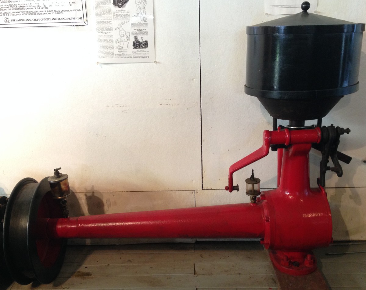
Rites Rice & Sargent Governor at the NEWSM.
263. The safety device attached to the Sargent Governor is illustrated in Fig. 163. Its construction and action are as follows: The bracket 36 is rigidly attached to the crosshead of the engine. It carries two pins, one 32, to which the safety trip weight 30 is pivoted, and the other 35, to which the safety trip weight spring is attached. After the engine passes a certain speed the inertia of the weight 30 overcomes, at the end of the engine stroke, the tension of the spring 33, causing it to rock forward about 32 and strike the bent rocker arm 28-25, and thus to move upward the push rod 24. This also pushes up the releasing lever 19, which turns freely on the pin 18 in the governor arm 16. The safety lever 52 is then released, because the pin 46, which is part of the releasing arm 19, is moved up out of the way of the pin 45 which is on the safety lever. This lever is now free to turn counter-clockwise under the action of the leaf spring 54 and to rotate with it the shaft 56 and the arm 51, thus moving the governor rod 50. As this rod moves to the right it will be seen, by referring to Fig. 159, that rod 5 will move to the right, that the governor rocker 2 will turn clockwise, and that the control pins 8 and 10 will be so far to the left that the cam lever 9 may not even permit the toe 19 to engage with the latch 14. If it does not so engage, there will, of course, be no motion of the live-steam valve and no steam admission, as explained in paragraph 252.
264. Some of the details of construction, although not necessary to, and not used in the above explanation of the governor action, are shown in Fig. 163 as follows: 4 is a spring plug to which the governor spring is attached; 5 and 60 are adjusting screws acting on the spring plugs for regulating the governor spring tension; 6 is a cored opening for the insertion of the guide rod 9 (there is another and similar guide rod in back); 8 is one of four weight plugs for guiding the rods 9, 9; 27 is a stationary bracket fastened to the engine frame; 34 is a pin on an arm of the safety trip weight which acts as a stop against the surfaces 37 when the weight 30 moves a sufficient distance in either direction; 38 is a part of the crosshead of the engine; 39 are “shaft buttons” for taking the thrust of the vertical shaft and governor weights and mechanism; 47 is a stop block on the arm 52; 48 is a stop block on the releasing arm 19 which bears against the pin 45 and keeps the release arm from dropping when the engine is running regularly; there is another pin at the upper end of the push rod 24 which engages with a stop block 55 on the arm 52 and prevents the release arm 19 from dropping when the safety gear comes into action; 53 is a pin on the safety lever against which the leaf spring 54 acts when it swings the safety lever to the right, the spring itself being fastened to a bracket on the governor casing at its upper end.
Spring-actuated Dashpots
265. Either vacuum or spring dashpots are used on the Rice and Sargent engines. The principle of the vacuum dashpot has already been illustrated in Fig. 155. The Rice and Sargent spring-operated dashpot is shown in Fig. 164, where the rod 2 is the same as the rod A in Fig. 157, and also the same as rod 11 in Fig. 159. This rod is fastened into the dashpot plunger 12, Fig. 164, by means of a ball joint, so as to allow for the slight swaying action of the rod as its upper end moves in the path of the pivot 7, Fig. 159. The spring 1 is relied upon to start and push down the plunger 12 rapidly and thus to rotate quickly the steam valve and close the steam port after the toe has been tripped from the latch, thus taking the place of the vacuum in vacuum dashpots. As the plunger 12 is lifted against the compression of the spring, the air above the plunger escapes through the opening 17 in the dashpot body to the outer space 14- Air is admitted under the plunger, as it rises, through the lifting of the steel ball at 10 and through an adjustment valve at 8 at the end of the adjustment rod 5. This air, as the plunger falls, forms a cushion to bring the plunger to rest without noise or shock. During the fall of the plunger such air as is permitted to escape passes only through 8 into the outer case which acts as an air reservoir. The opening at 8 can be varied by turning the handle 3, thus varying the cushion as desired. At 4 is a set screw for the adjustment rod 5. The dashpot case is shown at 15. The pipe 7 is for connecting space 6 and 14 with the outer air when the casing 15 is set into a concrete foundation. Similarly, pipe 9 is for draining oil which collects in the casing.

Disengaging Clutches
266. A telescopic disengaging clutch that will throw the live-steam eccentric out of action and permit the valves to be operated by hand is indicated at L in Fig. 157, and is shown in detail in Fig. 165. The solid center rod 6 is the part of the rod T1 to the right of L in the Fig. 157, and the hollow rod 5 is the part to the left. When the handle 4 is in the position shown, the two parts are firmly connected as one solid rod because, first, the teeth 3 on the arm 4 are in engagement with the teeth 2 on the rod 6, and second, the ends of the arm 4 fit snugly against the two collars 7, 7, which are fastened to the hollow rod 5 by set screws. When the handle 4 is thrown about one-quarter turn to the position 8 the teeth 3 of the handle simply move into an open channel or groove 1 in the rod 6, while the teeth on the rod 6 remain in their stationary position at 2. The groove 1 is slightly wider and deeper than the teeth 3 on the handle and so the rod 6 which receives its motion from the eccentric is free to slide back and forth without driving the part of the rod which leads to the steam valves. An exactly similar disengaging clutch is used on the exhaust clutch rod.

SETTING OF VALVES AND ADJUSTING OF GOVERNOR AND RODS ON RICE AND SARGENT ENGINES
267. The proper and best setting of valves, governors, and eccentrics, and the adjustment of rods and levers of valve-gear mechanisms for a given set of conditions involves, fundamentally, a thorough understanding of the layout or design of the valve gear. From this a set of directions may be, and usually is, written by each engine manufacturer and sent out to operating engineers, where their engines are installed. Such directions, as prepared by the Providence Engineering Works in connection with their Rice and Sargent Engine, are given in the following paragraphs.
Setting Valves and Eccentrics
268. For setting the valves, see that all connections are so adjusted that the rocker levers are plumb, then turn the eccentrics around on the shaft and see if the eccentric rod is adjusted so that the levers will travel equally each side of the plumb line. Now place engine on the forward center and make coinciding marks on the crosshead shoe and the slide, then move engine backward so that those lines will be 1/4 to 5/6 inches apart, then move steam eccentric around on the shaft so that the valve and port will be line and line, and moving to open.
For the exhaust on the high-pressure side, move the engine back about 3 1/2 inches and set eccentric so that valve and ports are line and line and moving to close the proper valve. Then turn engine on to the back center and do the same thing, only turn engine back more than 3 1/2 inches and then move engine up to the marks the way the engine is to run, so as to get out all back lash. If marks do not come exactly the same as at the front end, make up half the difference on the eccentric rod and move the eccentric so the lines on valves and ports come together again. Then do over the whole setting again. Try at all times to keep the length of the rod connecting the two rocker levers so that the two levers will be plumb at the same time.
On low-pressure side, the steam valve should be set to open about 3/8 inch from end of stroke and exhaust valves close from 6 to 8 inches from end of stroke. On tandem engines make a mark on front end of high-pressure sole plate clamp when engine is cold, then note the amount the high-pressure cylinder moves back after the engine is thoroughly heated, then lengthen out the long clutch rods the same amount. This will make valves in high pressure about the same as if set with engine hot.
The steel plates on latches and toes should lap by each other when engaged, 1/16 inch on cylinders up to 22 inches diameter; 3/32 inch on cylinders from 24 to 30 inches, and 1/8 inch on cylinders above 30 inches diameter. The “gap” or distance the steel plates move by each other before engaging is adjusted by the dashpot rod and should be kept as small as practicable; 1/16 inch on small cylinders to 1/8 inch on larger ones.
Setting the Governor
269. All parts of the governor should work freely and all cut-off connections should shake freely endwise on their pins. Governor cross shaft must be perfectly free.
Governor may be made more sensitive by screwing one or both the plugs out of the spring, and less sensitive by screwing those plugs into the spring. One-half turn of one plug is enough for a trial. This operation necessitates taking the spring out of the governor and putting it into a vise.
To make the engine run faster, turn the spring screws so as to put more tension on it. The reverse operation will make the engine run slower. One turn of each screw will usually make a difference in speed of about one revolution of the engine. Keep ends of spring equally distant from the weights.
Adjusting Cut-off Rods
270. In adjusting the cut-off rods for high-pressure side of compound engines and for simple engines, adjust the rod from governor to forward valve gear so that the latch at the front end of cylinder will just let go for the latest cut-off, with governor on stop. A good way to determine this is to adjust rod with engine running slow, so that latch will barely hold on and not let go. Then shorten the rod about one-half turn and the latch will always be sure to let go and give the governor the greatest range of cut-off obtainable. Also when the governor is at the top or bottom of cam slot the latch should clear the toe and prevent opening of steam valve. Then square up the cutoff by adjusting the cut-off rod between the front and back bonnets.
In adjusting the low-pressure cut-offs, get the valves square so that the cut-offs will be equal on front and back ends, by means of the cut-off rods between the front and back bonnets. Then adjust the cut-off rod from governor cross shaft so as to get the receiver pressure desired. This with steam pressure of 100 to 150 pounds for rated load on condensing compound engines will be in the neighborhood of 10 to 15 pounds; on non-condensing compound engines, from 36 to 40 pounds. Low-pressure cut-off should always be so adjusted as to allow low-pressure steam valves to open slightly when governor allows toe and latch to pass each other on high-pressure side. This adjustment is made when the proper receiver pressure is obtained and not in foregoing. This adjustment will prevent racing on light loads, and in getting ready to put on load.