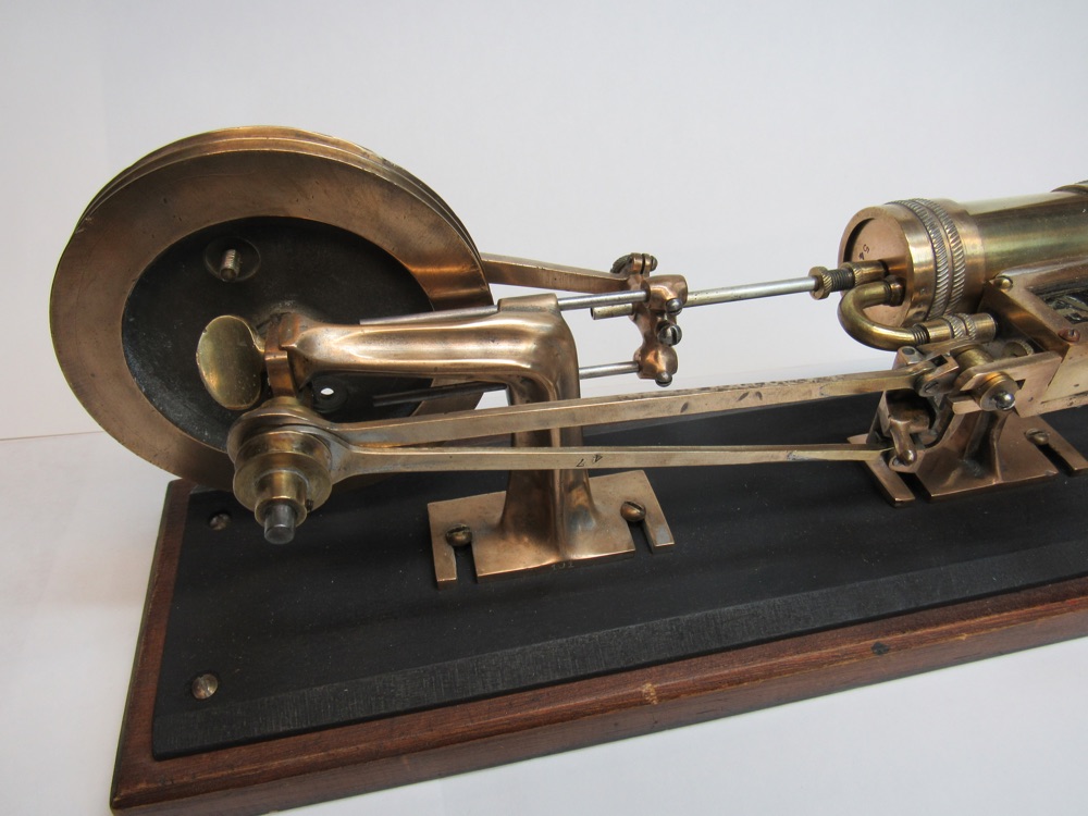
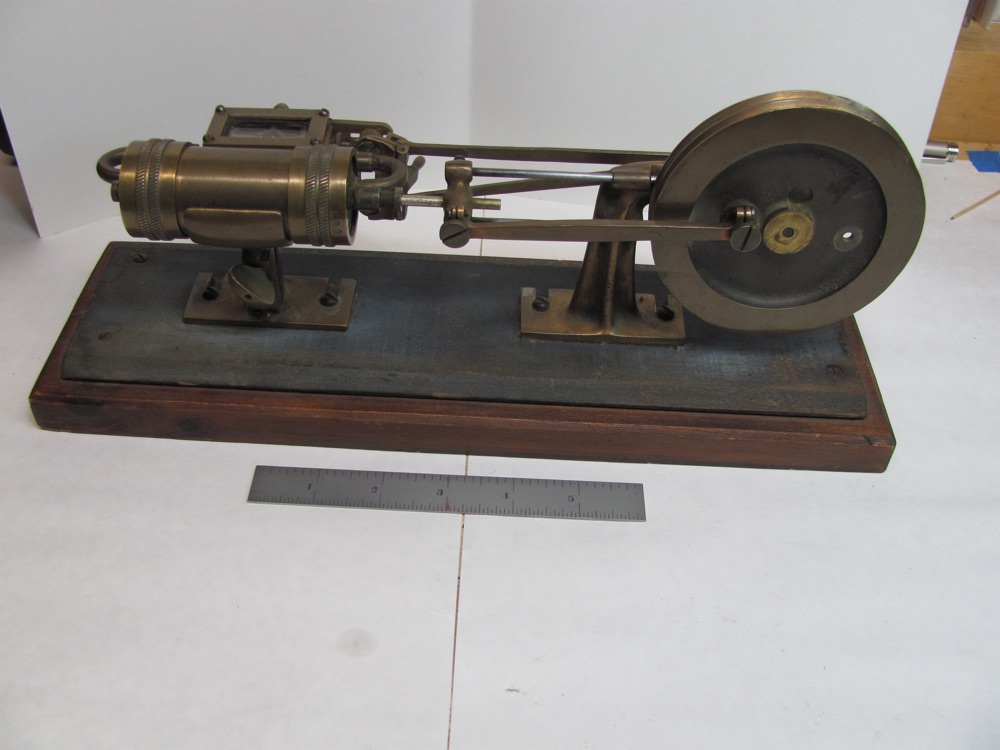
I was recently able to purchase the engine which is the subject of this article via an on-line auction and I was curious regarding its origins and somewhat unusual configuration. The condition of the wooden base along with the aging that appears on the metal parts indicates that it is old, but so far I have not been able to approximate its age. The engine is shown in Photo 1 in the ‘as received’ condition before any clean up or adjustments. The overall size of the base is 13 ¾” x 4 3/8”. The cylinder has a 15/16” bore and is adjustable for 1.5” or 2” stroke. The flywheel is 4” in diameter.
Description of the model and some of its characteristics
- This model includes several knurled screws and thumb screws allowing for ease of disassembly and adjustment.
- Nineteen of the part types are stamped with numbers as listed in the Table.
- There is a glass cover for the steam chest.
- Originally many of the parts were plated with a silver colored metal, but now most of this has been polished and/or worn off and it only remains in nooks and crannies.
- The two eccentrics driving the slide valve are independently adjustable and there is an adjustment screw for balancing the valve motion.
- The connection between the piston rod and crank arm includes a separate lock screw (not visible in Photo 1) that allows for adjustment of the cylinder stroke at ½” of 2”. There are many small dents in the aluminum piston rod indicating that the engine was run with and without equal distances to the inner and outer cylinder heads.
- There are two power take off sheaves, one at 1/2” diameter and a pair of grooves on the 4” dia. flywheel.
As with most of my model engine restorations, I took many photos and measurements, carefully disassembled the engine while keeping track of which parts go where, measured screw threads, and cleaned and lightly polished things. Photo 2 (after restoration) is a detail of the eccentrics, eccentric rods, fly wheel bushing thumb screw, and the fly wheel pedestal. The back side of the cross head shows a small screw in the center used for setting the symmetry of the piston in and out strokes.

Photo 3 is a side view of the steam chest and valve control lever showing the reversing linkage and the valve stem adjusting screw. The control lever also includes a neutral position. As received the steam chest was not parallel nor central to the cylinder. After disassembly and cleanup I was able to get somewhat better alignment between the chest and cylinder by adjusting the knurled couplings on each side of the steam chest.
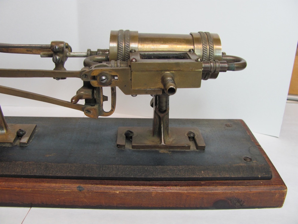
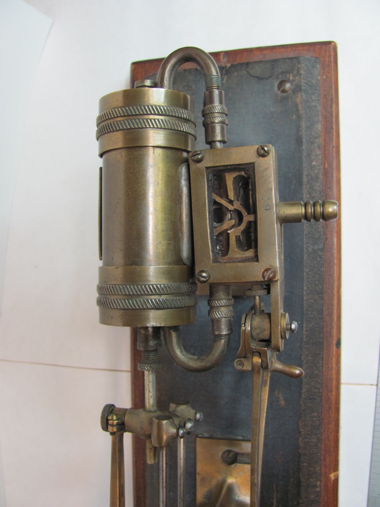
Photo 4 provides a good illustration of the steam chest cover with its glass view port. Interestingly, there are three brass screws and one copper screw attaching the steam chest cover.
The cylinder assembly includes a thick-walled brass liner held in place by friction of the cylinder heads (part #54) and the knurled cylinder head cap rings (part #132). The cylinder liner contains the only text on the engine, with “Bunting – Made in U.S.A.” embossed into it. The outer cylinder is a thin brass tube also held in place by friction using the cylinder head cap rings. There are two settings on the flywheel for the connecting rod – one for 2” stroke and another for 1 ½” stroke. In order for this double acting engine to operate correctly, the cross head location on the piston rod would need to be moved by ¼”. The aluminum piston rod has many small indentations from the adjusting screw indicating that other locations were tried, perhaps with an interference fit between the piston and cylinder heads! I wonder if the two power take-off sheaves were used with some kind of dynamometer to assess engine efficiency with various piston stroke settings, and various valve settings.
Getting the model running again
The biggest challenge in getting this engine running again was to reduce the air leaks in the steam chest. As received there were several layers of paper packing between the cover and the glass window, but also additional layers between the glass window and steam chest body, making a seal to the D-valve impossible. I first machined an acrylic window but was never able to get a good seal between it and the sliding D-valve. I expect the 10 psi air pressure that I was using was bowing out the window. I then reverted to the original glass window, without any of the paper layers between the glass and the steam chest. I finally had to apply a thin layer of translucent Teflon grease to the mating surfaces, including the valve. This grease is visible through the window and a little unattractive, but it is viscous enough such that it stays in place under the 5 to 10 psi that I now use to run this engine.
Could this be a related model?
While perusing the collection of photos from the 2015 Cabin Fever show posted on the NEMES site by Errol Groff of the New England Model Engineering Society, I quickly took notice of the engine shown in Photo 5 and had to peer closer.
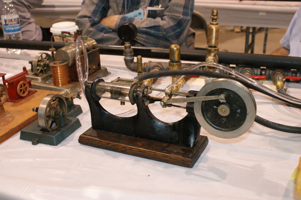
There are many identical or similar parts on this engine, including: (1) the flywheel with the number 66 cast into it (although on my engine the number is stamped), (2) the cross head casting with two round bar guides, (3) the 180° U-tube steam pipes between the steam chest and the cylinder heads, (4) the steam chest itself with the brass cover and glass view port, (4) the piston assembly with its inner and outer plates and stack of fiber seals (not visible in my engine until it is disassembled), (5) the knurled brass nuts on the flywheel and crank rod, (6) the D-valve, and finally (7) careful examination and comparison with my engine from the same viewing angle shows that there are two valve drive bars to a reversing mechanism. The clear class cylinder on this model is a nice addition if this is in fact a teaching model.
The owner of this engine is welcome to contact me via the editor. This engine will be a nice addition to my collection of model engines running on low pressure air at antique engine shows.
Numbered Engine parts.
| Part Number | Description | Notes |
| 1 | Steam chest | |
| 23 | Steam chest exhaust | .357×26 tpi |
| 28 | Cross head | |
| 36 | steam U-pipes | 1/4-32 |
| 45 | Piston rod | #6-32 |
| 47 | Valve control arms | |
| 48 | Crank arm | #3-48 |
| 54 | Cylinder head | |
| 57 | Inner eccentric | #3-48 |
| 59 | Crank pin | #8-32 |
| 66 | Flywheel | |
| 67 | Steam chest cover | #3-48 |
| 81 | Piston rod packing nut | 1/4-32 |
| 82 | Cylinder head plug | 1/4-32 |
| 101 | Flywheel pedestal | |
| 109 | Piston end plates | |
| 132 | Cylinder head cap | |
| 177 | Cylinder clamp lever | |
| E412 | Cylinder liner |