Type 94 Mark 3A Wireless Set
Mark 36 Transmitter
Mark 36 Receiver
The Type 94-3A transceiver was introduced in 1934 and was used by Japanese Army Division and Regiment stations in the field. The one tube transmitter is CW only using a Hartley oscillator. It has a frequency range of 400 kHz to 5.7 MHz by installing one of five different coils, or installing a crystal. The RF output is 15 Watts, it has a range of about 80 km, and is powered by a hand cranked generator. The five tube Super Heterodyne Regenerative receiver has a frequency range of 350 kHz to 6 MHz by installing one of five different coils.
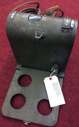
This transceiver was donated to the NEWSM by Richard A. Day. The radio is in new and unused condition and the original packing material was still inside of the shipping container when it was donated. The rotary switches are all frozen, but should not be difficult to them free up. Only the first of three transport cases was included in the donation. Fortunately the contents of the second transport case, the hand cranked generator, power cable, spare transmitter coils, headset, and key was included. The antenna wires from the second case were not included in the donation. The third transport case contained spare components, a flashlight, spare batteries, and a tool kit that held a soldering iron, a screwdriver, a pair of tweezers, a pair of pliers and a set of three wrenches joined at the center. One bag of a sectional antenna pole was included. The kit originally included an antenna wire, a ground, and guy wires. It was designed to be transported by a mule or several men.
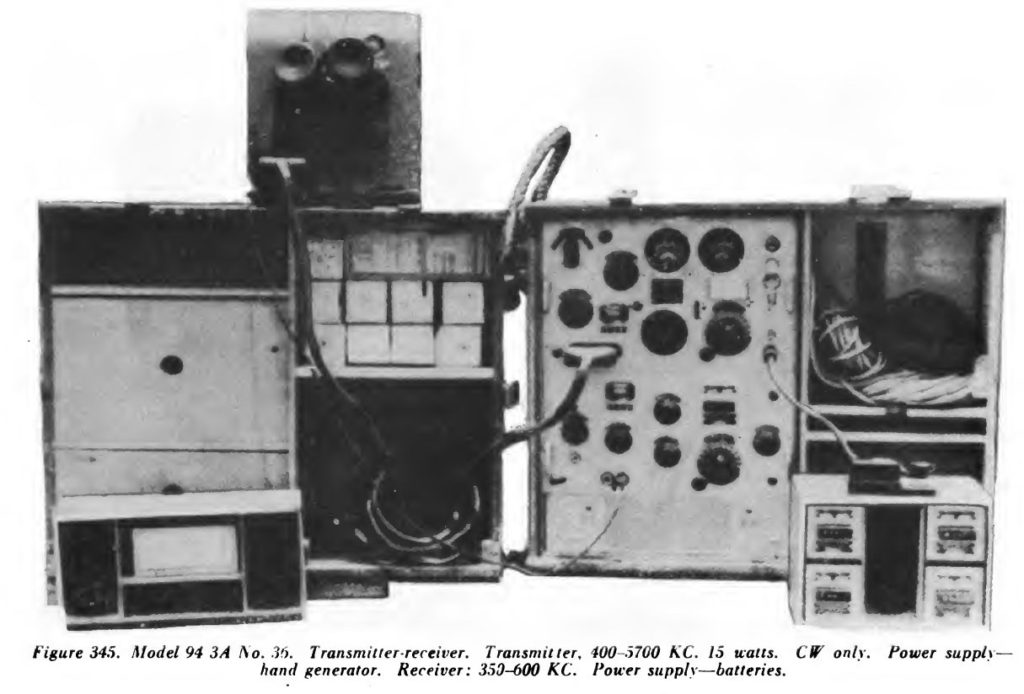 This image from the 1944 US War Department Technical Manual TM-E 30-480 Handbook On Japanese Military Forces shows all three transport cases. We only have transport case #1, the one shown at the right.
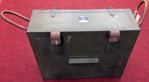
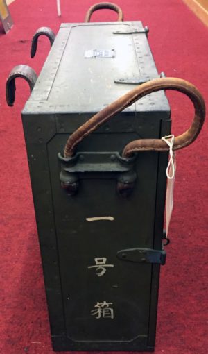
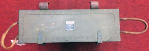
The images below show the details of Transport Case #1. Click on any image to see them in a slide show.
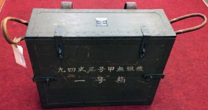
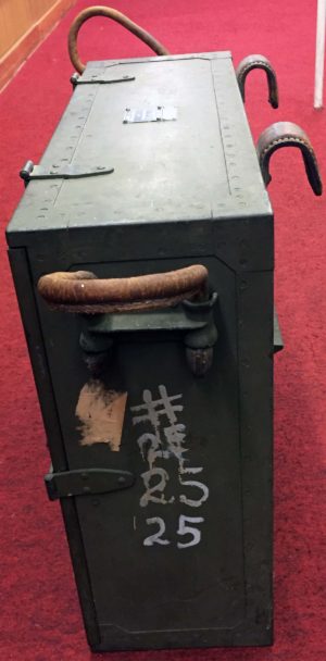
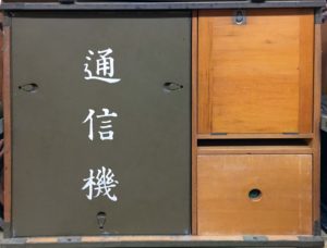
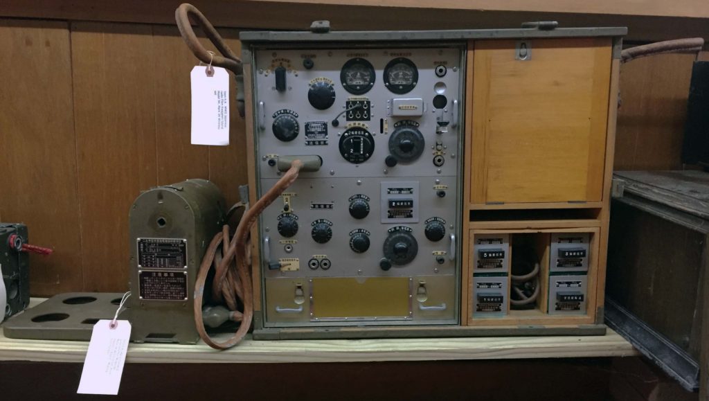
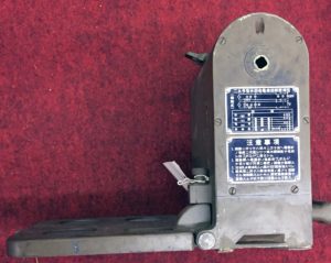
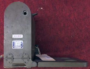
The image above shows transport case #1 and the hand cranked generator at the left. A metal cover snaps over the transceiver chassis, and has a schematic on the back. It is interesting to note that the information flow on the schematic is right-to-left, the opposite direction from western schematics. A wooden cover attaches to the front of the transport case.
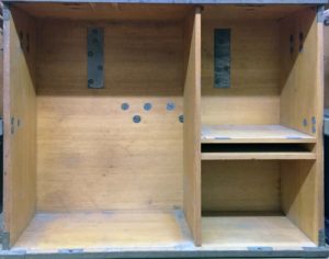
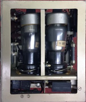
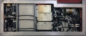
The transmitter is at the left top, the receiver is at the left middle, and the battery box at the bottom. All of these subsystems are held into the transceiver chassis by snap fasteners on the back of the chassis and easily slide out. The transmitter and receiver are wired together and to the battery tray through connections at the back of the transceiver chassis.
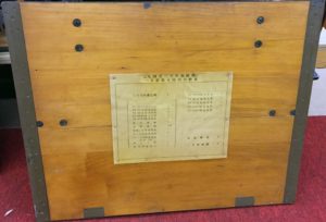
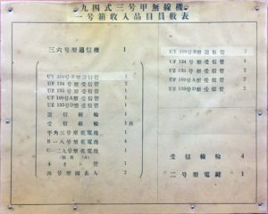
The drawer at the bottom right holds the four receiver coils that are not in use, and holds the Type-2 key for the transmitter. The compartment at the top right holds the calibration charts for the transmitter and receiver coils, headphones, leather carrying strap, and four spare coils the four transmitter coils that are not in use.
The other two transport cases held the generator, power cable, spare parts, and repair tools. A separate canvass case that holds tubular antenna pole sections was donated with this transceiver.
In 1941 the US War Department published a document TME11-227A Japanese Radio Communication Equipment. This document includes technical information for this transceiver that is repeated here.
TRANSCEIVER CASE
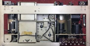
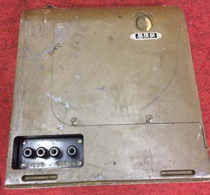
The Transceiver Case slides out of Transport Case #1. It has a removable front metal cover that is held in place with snaps. The schematic is on the back on the front cover. The Transmitter and Receiver are held into the Transceiver Case with snaps on the back of the Transceiver Case. The Battery Case is held into the Transceiver Case by snaps on the front of the Battery Case. There are three sets of electrical connections in the back of the Transceiver Case. The one with five connections supplies -3V, Ground, +1.5V, +67.6V, and +90V to the Receiver. The one with two connections supplies ground to the Receiver. The one with a single connection supplies the antenna from the Transmitter switch to the Receiver. The reference numbers on the connections are also on the schematic.
The images below show the details of the removable transceiver case. Click on any image to see them in a slide show.
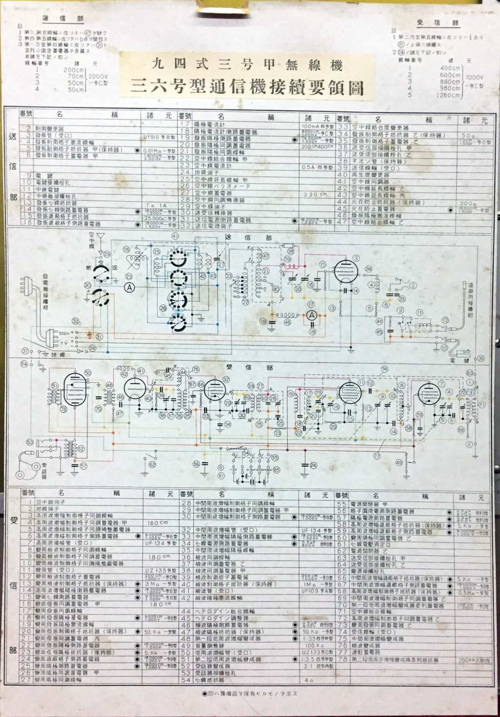 The schematic for the transmitter and receiver. Notice that the inputs are on the right and outputs are on the left.
TRansmitter
The transmitter is only capable of CW telegraphy, and has just one tube, a UY510B pentode. The RF output power is about 10W in the 400 kHz to 5.7 MHz range. The -7VDC for the transmitter tube filament and the 500VDC high voltage is supplied by a hand crank generator. The frequency can be controlled by a crystal or by tuneable self-oscillation.
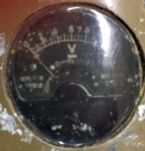
The transmitter is inductively coupled to a complex antenna circuit which is tuned by a combination of plugs and sockets, switches, capacitor, and variometer. This permits using any length antenna on any frequency. Tuning aids are a neon oscillation indicator coupled to the plate, antenna ammeter, and plate current meter. Keying is performed by connecting the high voltage negative lead to ground by three possible means: by a key with folding arm flush with the panel, by local key fitted with flexible lead, and jack or remote control and relay. You need to be careful with the key wiring because there is 500V on one of the wires.
The images above show the details of the transmitter. Notice the circles with the numbers inside. These numbers are on the Schematic and Bill of Materials. Click on any image to see them in a slide show.
![]() The spare transmitter coils. All of these coils have a serial number that matches the receiver.
The spare transmitter coils. All of these coils have a serial number that matches the receiver.
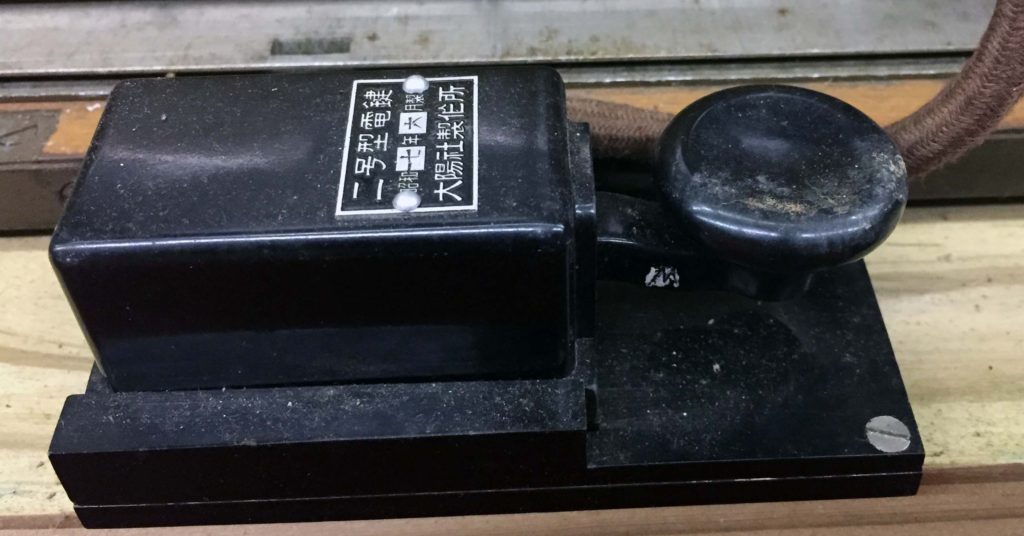
The external telegraph key.
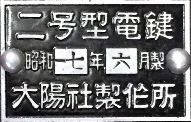
The label on the telegraph key.
Receiver
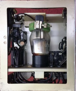
The receiver is a Superheterodyne design. It has five tubes; two UF134 pentodes, a UF109A triode, a UZI35 heptode, and a UZ133D triode-pentode. All of the receiver power us supplied by the batteries in the tray below the receiver. The receiver is six-stage Superheterodyne. R-f circuits are trimmed by adjusting circuit inductance and capacitance. Inductances can be reached from top of set when set is removed from case, but the RF amplifier tube must be removed before capacitors can be adjusted. The RF coupling circuit uses an autotransformer giving voltage step-up to mixer grid. A small band-spread capacitor on front panel permits fine tuning. The IF circuits are conventional. The Detector has Rheinartz type regeneration, controlled from front panel. Output of second detector is coupled to a triode section of last tube through step-up transformer. The triode output is coupled to a pentode section through an identical transformer. The pentode output is transformer-coupled to parallel phone jacks on front panel. Both high-voltage and low-voltage switches are located on front panel. The case cannot be closed if low-voltage switch is on. The overall gain of the set is unusually high, but is somewhat offset by heavy background noise.
The images below show the details of the Receiver. Click on any image to see them in a slide show.
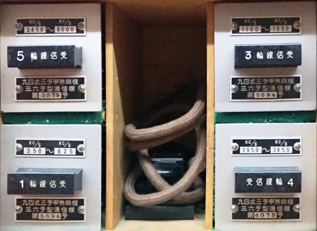 The spare receiver coils. Coils #1, #2, and #3 have a serial number that matches the receiver. Coils #4, and #5 are likely from a different serial number receiver.
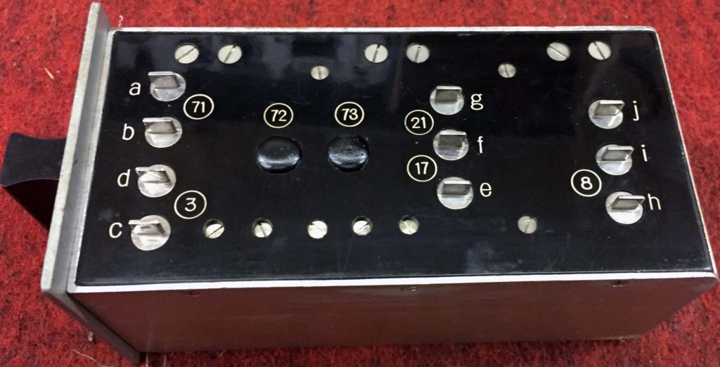
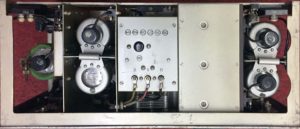
This image shows the details of the receiver coil connections. The letters indicate the electrical contacts, and are shown on the receiver schematic. The numbers are components, and are also shown on the schematic.
Batteries and Hand-Cranked Generator
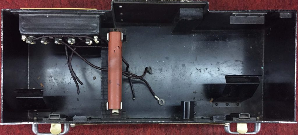
 The battery box that plugs in below the receiver.
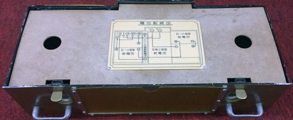
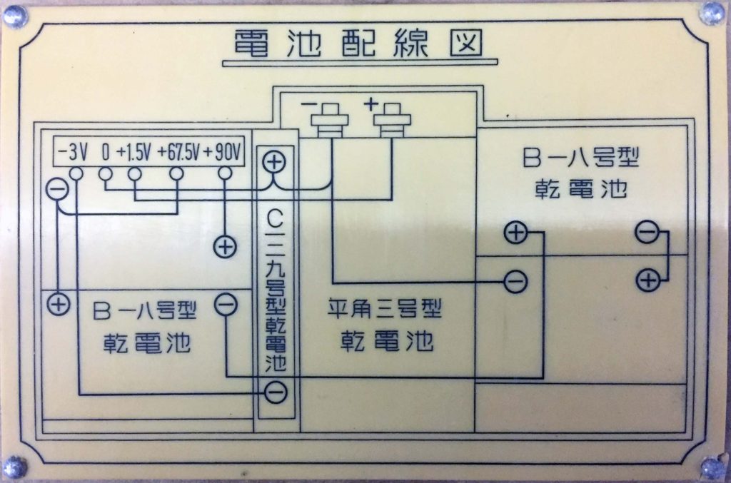 The battery box label. This shows four rectangular 22.5V B batteries wired in series to supply 67.5 and 90V. The middle holds a rectangular 1.5V A battery for the tube filaments. The orange tube supplies 3V for the grid bias. This may actually hold two 1.5V cylindrical batteries.
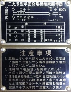
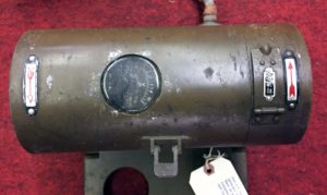
The images below show the details of the hand-cranked generator that makes 500 VDC @ 60 mA and 7 VDC @ 1.5 A for a total output of 40.5 Watts. There are two positions for a crank that turn on opposite directions. One WWW page that I found said that the two crank positions were for left-handed and right-handed people. The same WWW page said that you need to turn the crank about 60 RPM. The square hole for the crank matches an American 3/8″ drive for sockets. We might try spinning the generator with an electric drill to see if we can make enough power for the transmitter. Click on any image to see them in a slide show.
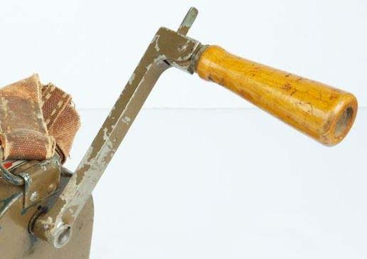
This is the crank that we are missing for the generator.
Facts from the TME 227A Publication
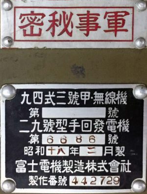
Design Date
Type 94 means that this transceiver was introduced in 1934, based on the Japanese calendar year of 2594.
Transmitter Frequency Range, 400 kHz to 5.7 MHz in five bands
-
- #1: 400 kHz to 500 kHz
- #2: 500 kHz to 1 MHz
- #3: 1 MHz to 2 MHz
- #4: 2 MHz to 3 MHz
- #5: 3 MHz to 5.7 MHz
Receiver Frequency Range, 350 kHz to 6 MHz in five bands
-
- #1: 350 kHz to 625 kHz
- #2: 625 kHz to 1.1 MHz
- #3: 1.1 MHz to 1.95 MHz
- #4: 1.94 MHz to 3.45 MHz
- #5: 3.45 MHz to 6 MHz
Receiver Power Source
The battery box at the bottom left of the chassis holds four 22.5V Type-18 Square B batteries, a 1.5V Type-3 Square A battery, and a 3V Type-39 Cylindrical C battery to make Grid Bias:-3V, Filament:1,5V@400mA, 67.5V, and Plate:90V@10mA.
Transmitter Power Source
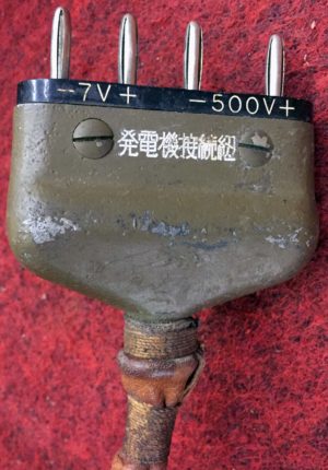
Hand cranked generator that makes 7VDC and 500VDC.
Antenna
65.5′ of stranded wire suspended between two 21′ sectional poles. Each pole section is 3′. Lead in wires are 26’9″ long. Two ground wires, a black one 33′ long and a brown one 66′ long.