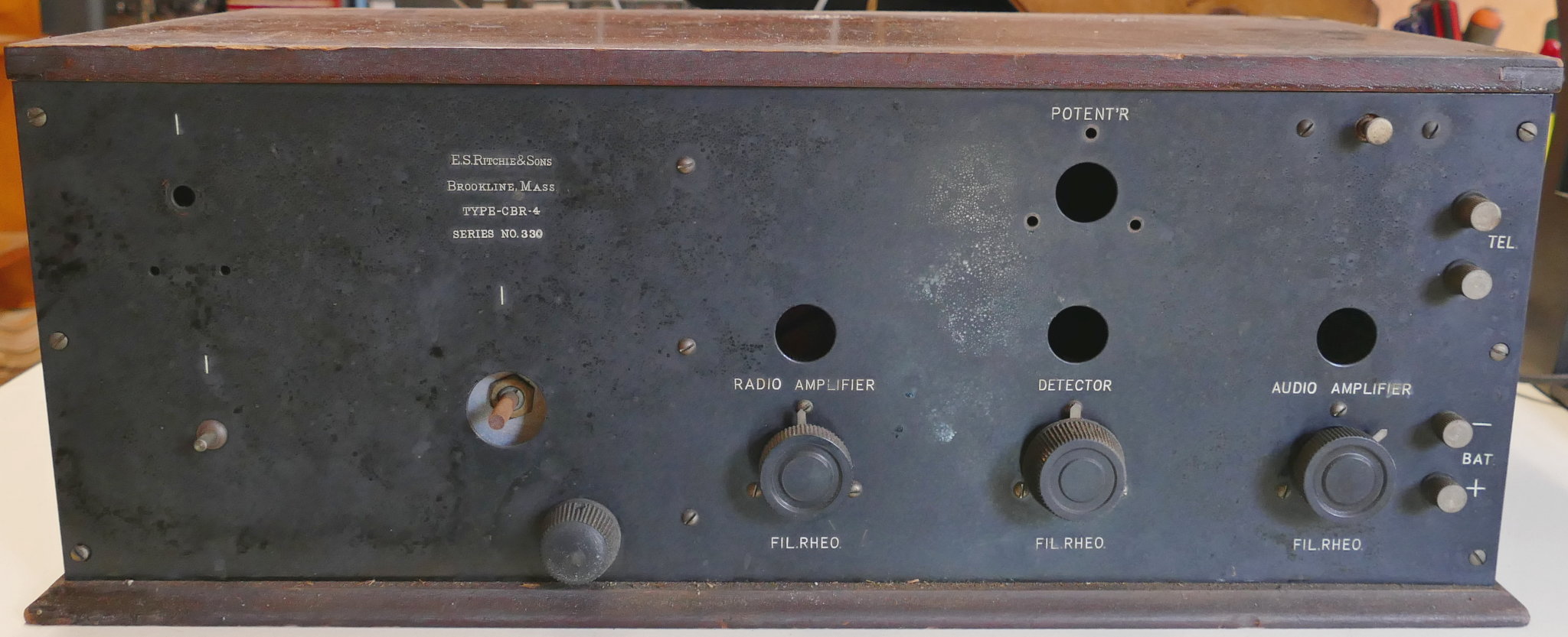
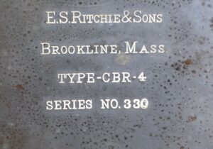
This TRF AM receiver was probably designed by Sewall Cabot of Brookline, MA. The missing main tuning knob should have a bezel that is labeled WAVE-LENGTH-METERS, CABOT-RADIO-AMPLIFIER, and TWO-CIRCUIT-SELECTIVE TUNER. The tuning range on the similar CBR-2 bezel is 470 Meters (600 kHz) to 170 Meters (1.7 MHz). The AM broadcast band in the USA is 540 kHz to 1.7 MHz.
It was suggested by another E.S. Ritchie owner that the Series Number is actually the Serial Number, so this one would be Serial Number 330.
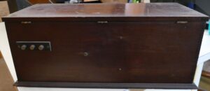
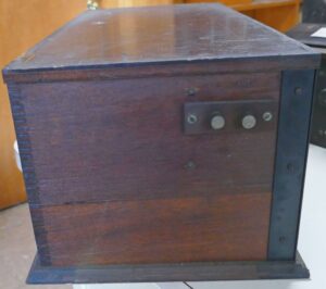
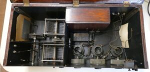
The receiver is built inside of a sheet metal case mounted inside of a wooden case. There are sheet metal dividers inside of the case to provide shielding between the tuning sections and the amplification section of the receiver.
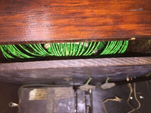
There are four tuning knobs on the front panel. The missing main tuning knob adjusts the mesh of two variable capacitors. One capacitor is connected to the antenna, and the other is connected to the balloon inductor that is inside of a wooden box. The smaller tuning knob to the lower right of the main tuning knob is connected to the variable capacitors by a reduction gear to provide fine tuning. The missing knob to the left of the main tuning knob adjusts a small capacitor that capacitively couples one tuning capacitor to the sheet metal case of the receiver. This is labeled Plate Vernier on the CBR-2 radio. At the top left is another missing knob that adjusts a small variable capacitor connected between the antenna and the sheet metal case of the receiver. This is labeled Grid Vernier on the CBR-2 radio. The NEWSM has some General Radio knobs that match the style of the existing knobs.
There are 3 vacuum tubes. Operating Instructions for a CBR-4 say that the the RF Amplifier and AF Amplifier tubes are 01A, and the Detector tube is a UV-200 or UX-200 Argon filled Gas Detector with a 1 Amp filament. The vacuum tube sockets, rheostats, and tuning capacitors were all manufactured by General Radio C0. There are holes in the front panel so you can see the brightness of the filaments in each vacuum tube. Three rheostats on the front panel adjust the current flowing to each vacuum tube. The rheostat knobs are labeled RADIO AMPLIFIER, DECTOR, and AUDIO AMPLIFIER above the knob and FIL. RHEO below each knob.
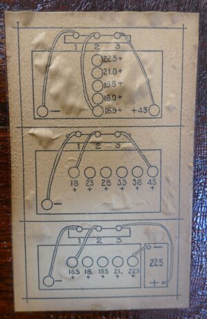
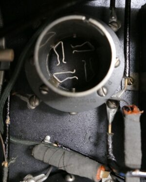
The resistor in the missing potentiometer above the Detector tube window connects to ground and the 6.3V A battery. The wiper on the potentiometer is connected to the ground for the 45V B battery and the 16.5V C battery. Thus lets you adjust the Grid & Plate bias +/- 6.3V. Since the potentiometer is wired across the A battery is needs to have a much higher resistance than the potentiometers for the filament voltage, and needs to have three electrical connections. We found a three-connection 400 Ohm General Radio potentiometer with the same mounting pattern and knob as the existing potentiometers in our parts collection and installed it. The resistance of the Radio Amplifier and Audio Amplifier potentiometers is 50 Ohms. The potentiometer for the Detector probably has a lower resistance because of the higher current of the UV-200 Detector Tube.
The +16.5VDC and +45VDC battery connections are on the rear of the receiver. The +6.3VDC filament battery connection is on the bottom right of the front panel. The filament power switch is on the top right of the front panel.
The missing audio transformer was identified as an ACME A-2 from images of other Ritchie receivers. We had several A-2 transformers in the collection and installed one that looks like it is new. The transformer couples the Detector Plate to the Audio Amplifier Grid.
The missing knob, shaft, and part of the variable capacitor that goes at the top left was loose inside of the chassis and has already been reinstalled.
Click on one of the images below to see a larger view.
We have very little information on this AM Radio Receiver. We will update this page as we learn more.
The E.S. Ritchie & Sons company was started by the physicist Edward Samuel Ritchie (1814-1895) in 1850. His first products were liquid filled marine compasses, which they still produce today. The company was originally in Boston and moved to Brookline in 1886. The 1908 Brookline telephone directory lists the address of E.S. Ritchie & Sons as 112 Cypress St, Brookline, MA. Google Maps shows this address as the Ritchie Building which is across the street from Brookline High School. At the same time Ritchie also partnered with Nathan B. Chamberlain (1809-1878) to form Chamberlain & Ritchie which manufactured mechanical and electrical device for teaching and experimentation. After Chamberlain’s departure in 1866, Ritchie continued to manufacture and sell the scientific instruments. After Ritchie’s death his sons sold the scientific instruments part of the company to L. E. Knott Apparatus Co.
The earlier CBR-2 receiver says CABOT-RADIO-AMPLIFIER, and TWO-CIRCUIT-SELECTIVE TUNER on the bezel of the tuning knob. We believe that this is Sewall Cabot. The same 1908 Brookline telephone directory shows that Mr. Cabot lived at 232 High Street, just 0.6 miles from the Ritchie Building. A few years prior to the manufacture of this receiver Sewall Cabot was on the Committee for the Organization of the Boston Section of the Institute of Radio Engineers. Sewall Cabot also designed the Cabot Reflex Receiver for the Acme Company.