This is an improved version of the original Model 10 “breadboard AM radio. The changes from the earlier version include eliminating the potentiometer that controlled RF amplifier grid bias and replacing it with an 800 Ohm damper resistor, and eliminating the bypass capacitors on the RF amplifier filaments.
The set uses two 201A tubes for the Radio Frequency section, a 200 tube for the Detector, and two 201A tubes for the Audio Amplifier. We could use a 200A tube with a thoriated tungsten filament for the Detector and reduce the total filament current by 0.75A. These were common tubes, so we should have plenty in the Museum’s inventory.
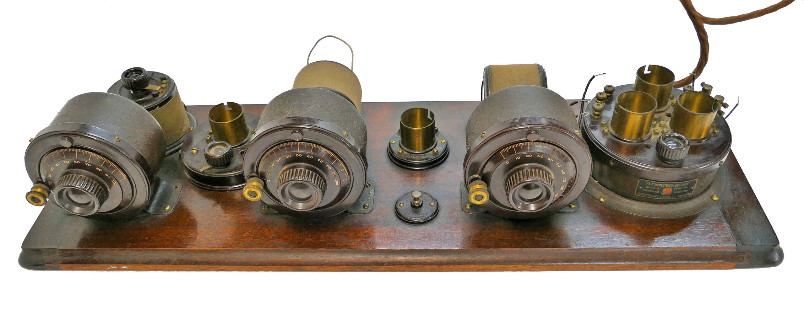
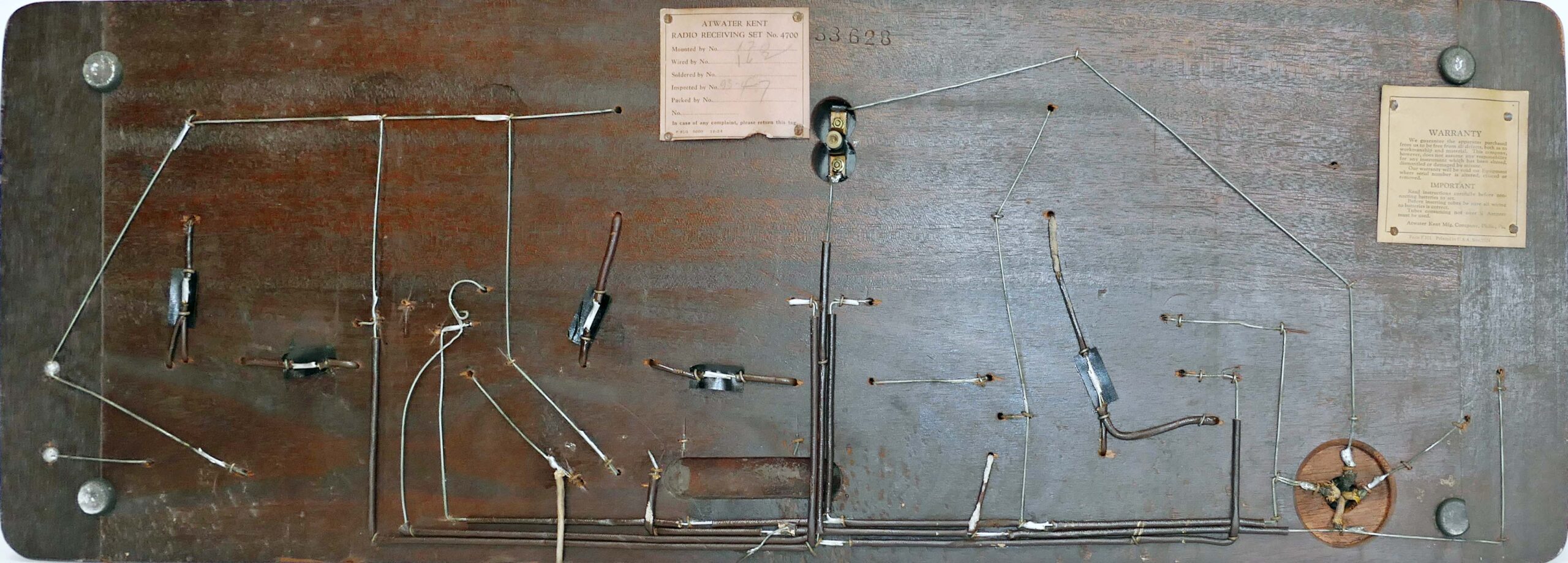
This radio is currently in the Wireless Workshop being restored. We need to completely disassemble the radio so we can clean the finish on the breadboard. The original finish is in good condition, so there is no need to replace it. The rubber washers on the fine tuning knobs will need to be replaced because they harden with age and will not turn the dial. We need to check the condition of the resistors, capacitors, inductors, and especially the transformers in the compartment at the right. We will also need to restore or make a Battery Eliminator to supply the +90VDC, +22.5VDC, and +6VDC to power the radio.
5/5/22
We measured the resistance of the audio transformers in the Detector/Amplifier island, and were surprised to find that they were OK. We connected it to the recently donated ARBE-III Battery Eliminator, installed the second audio amplifier tube, connected a speaker, and injected 1 kHz signal into the plate contact of the first audio tube. Nothing! We tried another tube, and got a tone out of the speaker. (We have quite a few 201/201A/301A tubes that we will need to test.) We installed the first audio tube and the detector tube, injected the audio signal into the IN connection on the island, and got a much louder tone from the speaker. We set the frequency generator to a 630 kHz carrier with 1 kHz AM modulation, and worked our way back through the RF stages to the antenna, peaking the tuning and testing tubes as we went. We connected a short antenna and could hear WPRO in Providence, RI. Our first Atwater Kent breadboard is now working!