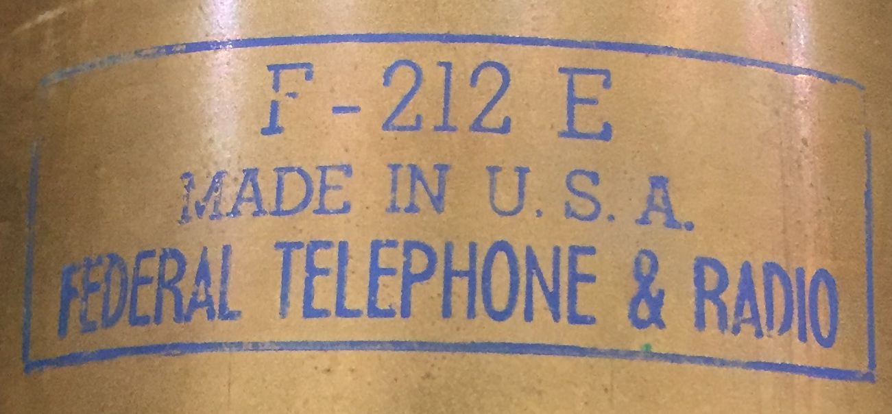
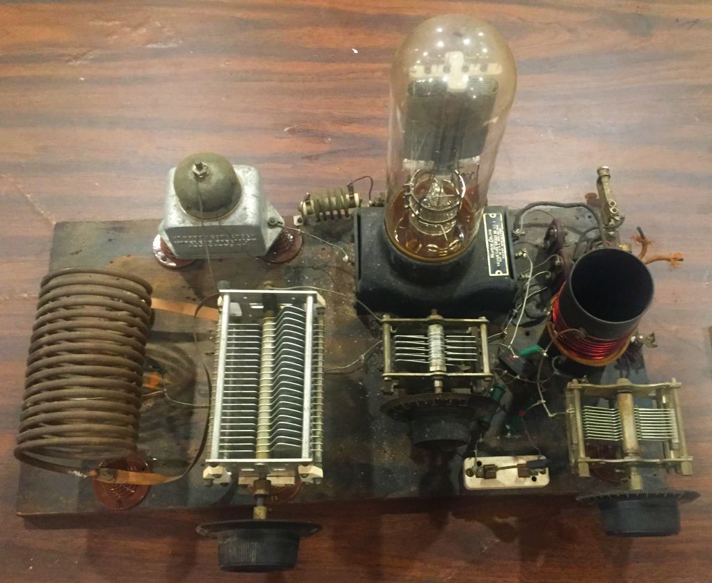
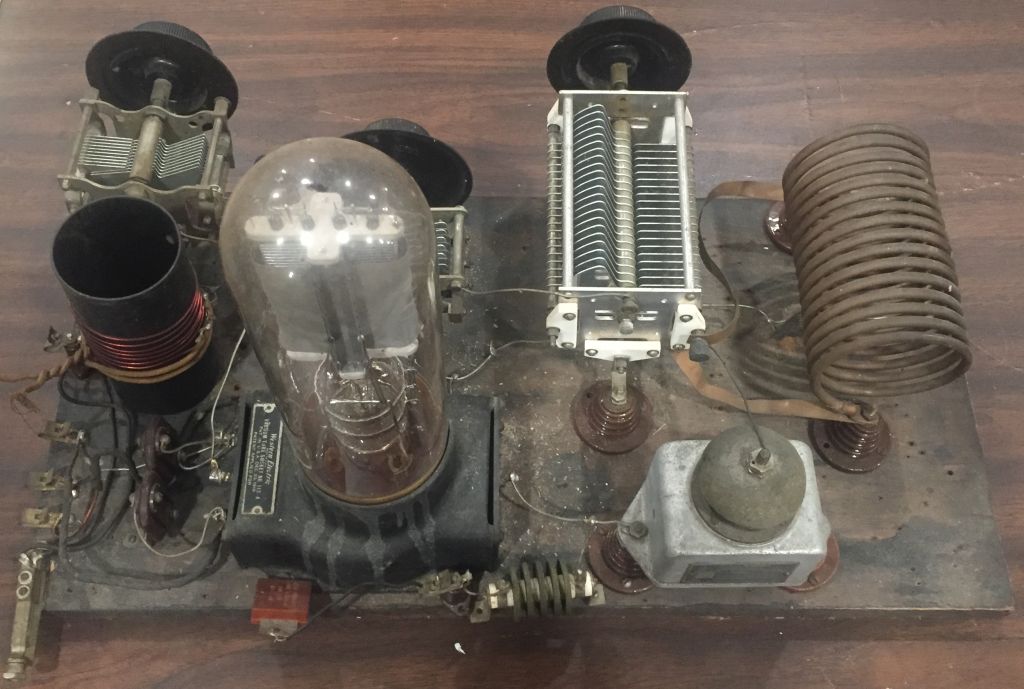
We have had many discussions about what this radio equipment actually is. Our current though is that it is a Tuned-Plate Tuned-Grid Transmitter, but that could change after more research. It has three tuning capacitors, so that makes us think that it is a TPTG design and not a TNT. As with TNT #1, it is similar to the plans in the December 1929 issue of QST magazine but without the updates published in the 1934 ARRL Handbook. This transmitter has an adjustable capacitance for both the Grid Tank circuit and the Plate Tank circuit, and a the third adjustable capacitor is part of the antenna tuning circuit. It has a really giant, more than 12″ tall, Federal F-212 E tube (14 V @ 6.25 A Filament, 1,500 Vmax @ 350 mA). From the tube datasheet, it looks like the tube could have an output of about 400 Watts. With 25% efficiency that means about 100 Watts at the antenna!
Click on an image to see a larger view.


