In the late 1920s there were many popular homebuilt CW transmitter designs; Armstrong Tuned-Plate-Tuned-Grid (TPTG), Hartley oscillator, Colpitts oscillator, and Tuned-Not-Tuned (TNT). Most of these designs had multiple adjustments and were difficult to tune for optimum operation. The December 1929 issue of QST magazine includes an article by George Grammer of the A.R.R.L describing how to make an easy to use Single Control CW transmitter.
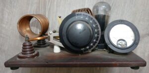
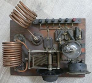
This TNT transmitter in the NEWSM collection was built according to the George Grammer article, but with improved antenna coupling from the TNT, Antenna Coil Version, ARRL Handbook, 1934. The TNT transmitter design is based on the Armstrong Tuned-Plate-Tuned-Grid (TPTG), but has a fixed grid tuning circuit to simplify operation. The name Tuned-Not-Tuned (TNT) means that it has a tuned plate circuit, and no tuned grid circuit, making operation simpler. This transmitter design also depends on the antenna being constructed to work at the frequency range of the transmitter which eliminates the antenna tuning circuit.
Click on an image for a larger view.
We plan to get use this transmitter for the AWA Bruce Kelley 1929 QSO Party that will be held on Saturday November 11 2300 UTC to Monday November 13 0300 UTC, and Saturday November 18 2300 UTC to Monday, November 20 0300 UTC. 160, 80, 40 and 20 Meters. The QSO Party typically operates between 1800 to 1820 KHz, 3550 to 3570 KHz, 7050 to 7070, 7110 to 7125 KHz, and 14060 TO 14070 KHz. We will operate about 3550 KHz.
The 1934 AWA TNT article shows three possible sets of plate & grid coils. Ours has just one set with 12 turns for the plate coil and (probably) 60 turns for the grid coil. This will configure the set to operate about 3.5 MHz (80 Meter), which is one of the bands that is used for the QSO party. We should make additional coil sets with 5 & 25 turns for 7 MHz (40 Meter), and 3 & 9 turns for 14 MHz (20 Meter).
We also need to make a power supply for the transmitter. Our TNT set has a single RCA UX-210 tube installed. The RCA datasheet says that the filament needs 8 V @ 1.25 A, and the plate current & voltage should be in the range of 12 Ma @ 250 VDC and 22 Ma @ 425 VDC. The UX-210 tube can handle about 1.5 W. We could also use a Type 01-A tube with a 6 & 135 VDC supply, a Type 10 tube with a 7.5 & 500 VDC supply, or Type 45 tube with a 2.5 & 350 VDC supply in this transmitter. We have lots of vintage power supplies in the collection. If we find one that matches one of these tubes, it might be easier to repair the vintage power supply than to make a new one.
On 10/12/23 we powered this transmitter using the power supply from TNT #2. We quickly found that the vacuum was gone from the RCA UX-210 tube. We borrowed the Sylvania VT-25-A tube from TNT #2, but didn’t see any continuous RF oscillations. Replacing the grid-leak resistor solved that problem. Now we have two TNTs to use for the AWA Bruce Kelley 1929 QSO Party.
References for TNT (Tuned plate Not Tuned grid) transmitter
- Building A 1929 Style TNT Transmitter, well illustrated build by VE7SL, Steve McDonald
- Planning and Building Transmitters, form 1934 ARRL Handbook (also referenced in above text)
- The Planning and Building of an Award-Winning TNT, by Nigel Wiegand, W0VLZ. Includes links to
videos of the TNT transmitter that he built. - The Saga of the TNT Transmitter, 1981 story of how W2SN addressed numerous hurdles while
building his TNT transmitter - The Single Control Transmitter, by George Grammer, Dec., 1929 QST (also referenced in above text)
The TNT – A 1929 Single Control Transmitter, by Steve McDonald, reference on the Antique Wireless
Association Project Files page. - Vintage CW Transmitters, by Gary Poland. Illustrates and describes several reproductions of classic
1920's transmitters, including the TNT built by Gary Poland, W8PU