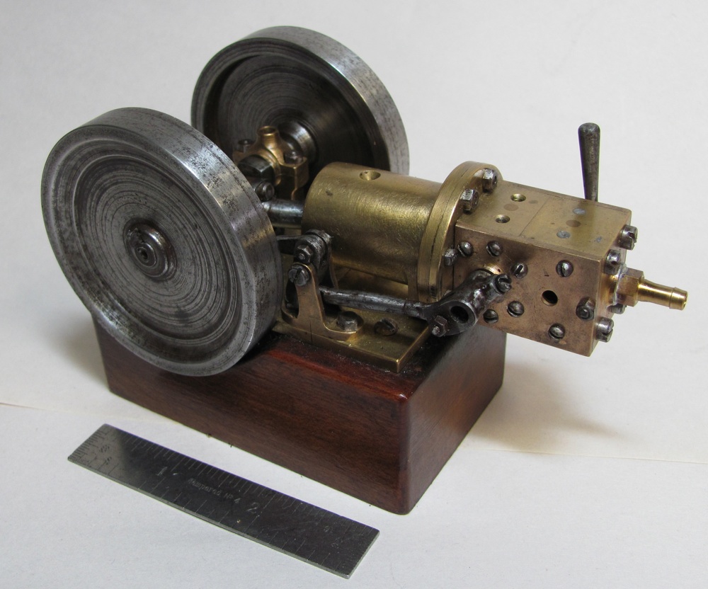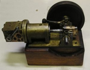
In this photo, one of the flywheels has been removed to see the state of the engine as it was when received. Most hard to reach surfaces had a thick layer of grime and all of the steel components were quite rusty. The place where compressed air was admitted to the valve chest showed a small residue of solder, but the connection was missing. The first step in restoration is to photograph the engine from all angles to document the condition of the model and to help in reassembly. Prior to disassembly it’s a good idea to assess how fasteners will be removed and in what order to avoid inadvertent damage. Parts bins or segmented cases with labels are a useful to allow for temporary storage of small parts and fasteners. For this engine, most of the fasteners are slotted screws simply requiring an assortment of the correct size screw drivers.
The hex nuts presented an interesting challenge. The hex nuts holding the valve chest to the cylinder were measured and showed two sizes; the larger nuts were 0.165 inch across the flats and were threaded size #2-56. I decided that these nuts would require an 11/64 inch spanner wrench for removal. In a similar manner, the smaller nuts were 0.135 inch across the flats with the same #2-56 thread and would require a 9/64 inch wrench. After a futile attempt of Internet searching for 9/64 and 11/64 wrenches, I determined that I would need to make my own. Starting with a ¼” by 3/32” steel bar about 2” long, I used a 1/8” end mill to form the ends into the desired spanner wrench shape which is shown in photo 3. A little filing rounded the sharp edges.
Now that disassembly could proceed, I carefully began loosening and removing screws and nuts. The small steel round-head screws on the sides of the valve chest were stubborn and I had to carefully ensure that the screw driver blade fit tightly into the slot so as to not distort the screw head. The four #5-40 screws holding the valve chest to the cylinder were even more stubborn but, with liberal application of WD-40 and time to soak, they were eventually coaxed out. These screws were heavily rusted and are in such tough shape that they’re scheduled for replacement someday. In my opinion, when restoring an old engine it is necessary to remove dirt, grime and rust but this must be done without inadvertently removing or blurring any details of the parts.
Screws and nuts were cleaned up with fine grit emery paper. One particularly vexing aspect was the interference fit between the 9/64 inch nuts on the valve chest and the small screws in the sides of the valve chest. It took a significant amount of finesse to coax the nuts off while holding the chest partway off from the cylinder. If parts have been distorted due to negligent use of hand tools, careful use of a fine metal file is made to return the shape to as close to the original as possible.
One debate that can arise has to do with loose motion in the valve linkage. This engine had some slop in the crank bushings, in the eccentric strap relative to the eccentric, and in the valve linkage connections. I decided to see how well the engine ran with the linkage as is, so hopefully no modification would be required.
The flywheels were particularly rusted and included some deep pitting in a few places. I was able to mount them one at a time on a tapered mandrel between centers in my lathe and, with the use of numerous small pieces of emery paper, clean up most of the rust. I decided that I didn’t want to take off any metal if I could avoid it, so a medium brown color of residual rust in crevices remained.
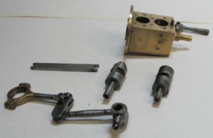
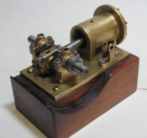
This photo provides some details of the workings of this engine showing the two rotary valves, valve chest, eccentric and valve linkage. The eccentric strap arm is an interesting construction with a brass section bonded to a steel section. The following photo provides an additional view of the cylinder, crankshaft and bearings with the fly wheels removed.
Once everything was cleaned it was time to consider reassembly and the application of compressed air. But first I needed a replacement for the missing air inlet. I decided to use a barbed hose connection suitable for 1/8” ID, 1/4” OD tubing. The barbed fitting was machined from 3/16” brass hex bar and was silver soldered to the inlet port. I decided that in the future if this proves to be inappropriate it would be easy to mill off this piece.
The engine parts were oiled and reassembled while checking that parts turned easily and nothing was binding. I noticed a story mark on the valve support arm which needed to line up with the base plate. This can be seen if one looks closely at the center of the top right photo. (Click on image to enlarge.) The flywheels were reinstalled with their locking pins and light oil was applied to all moving parts. (I prefer to use SAE #10 machine oil as I believe it is cleaner than engine oil.) I ran the engine in both directions by hand using the flywheels and everything seemed to run smoothly.
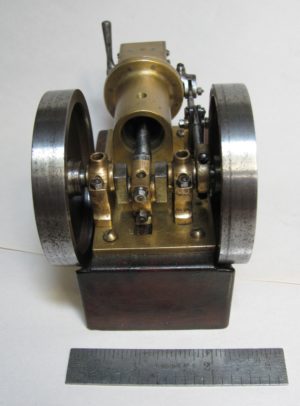
Upon the application of air I got the engine running in one direction with about 10 psi and was quite happy, although it didn’t want to run in the opposite direction. At first I thought I would have to deal with some of that slop I knew about in the bearings and valve linkage, but after about 10 or 15 minutes of operation I had to reduce air pressure in order to maintain a reasonably slow engine speed. Eventually I was down to about 3-4 psi and she was running quite smoothly. At that point I threw the reversing level over, and we had operation in both directions! I was successful in getting this sweet little engine cleaned up for presentation and running on less than 4 pounds of air. I expect that the machinist who created this little gem would be quite pleased.
