As a novice machinist I was pleased to receive my Sherline mill and use it for some simple milling operations. As my skills improved, and my projects tended to get smaller, I was unhappy with the Sherline mill vise with its 1.5” wide by 1” deep jaws. Too many times I had to make special jigs or other accommodations to hold small parts. I wasn’t aware of any suitable size mill vises that I could purchase so I decided to design and build my own scaled-down version.
The plans in this article show the result – a mini-mill vise with ¾” wide jaws by about ¼” deep. The mill vise body (1) starts from a length of ¾” brass square stock. Steel could be used for the body to provide more rigidity but I’ve found after 10 years of use that the brass has been holding up fine (with the exception of a few minor bruises from errant mills and drills).
The first step is to square the sides, top and bottom with a fly cutter to ensure alignment accuracy to the mill table. Removing about 0.005” from each side should be plenty.
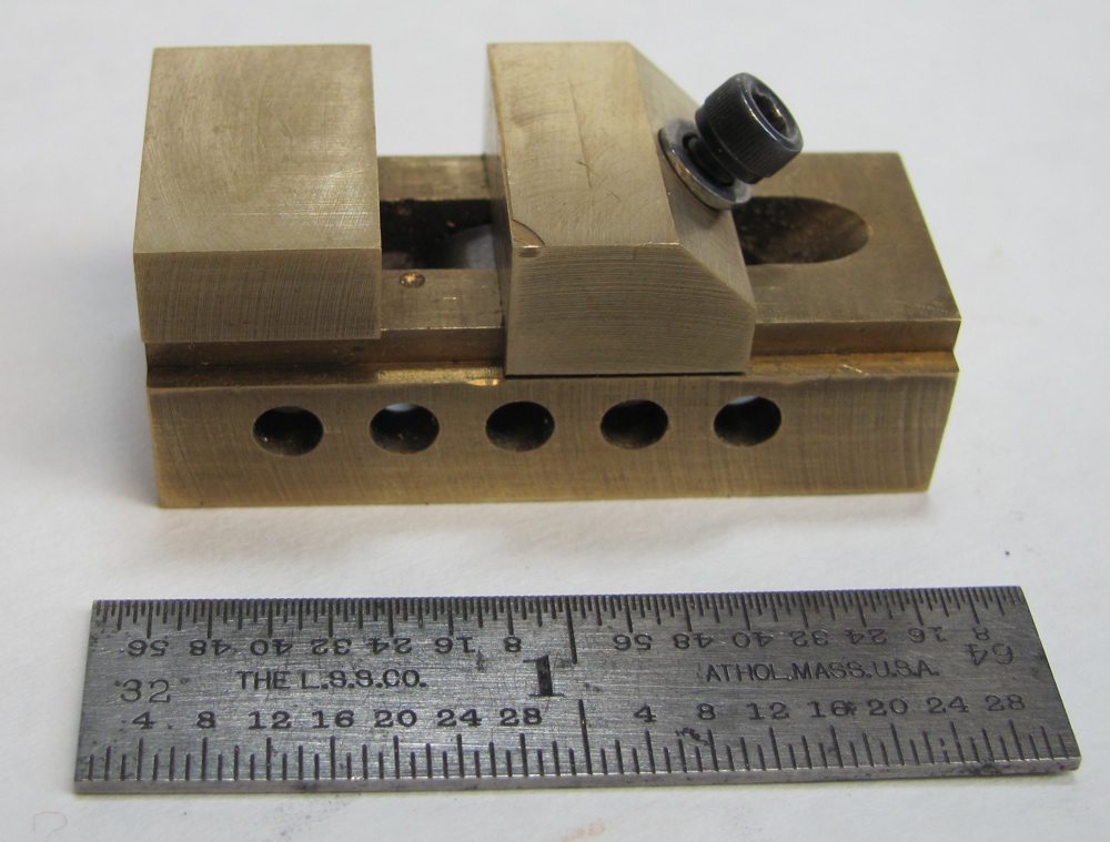
The next step is to drill the register holes for the pull down nut. In photo 1 you will notice 5 register holes – the result of my early attempt at maximizing the reach of the moveable jaw (2). Being a little impatient, and not having CAD tools, I proceeded with my design without doing an assembly drawing, which was a mistake discovered upon assembling and using the vise. The 3 center holes are all that are needed for full jaw movement from fully closed to an opening of about ¾” using a #6-32 by ¾” long cap screw.
After drilling the holes, mill out the bottom two cavities (.25” wide and .47” wide) which are located on the centerline of the vise. The register holes should have a semi-circular profile within the .47” slot. Flip the body over and mill the .47” high feature. An angle plate is a handy method to mill the end of the .25” slot to 45o for the pull down screw clearance. Now mill the two .12” slots and you’re mill vise body will be compatible with standard Sherline hold down clamps. I break all sharp edges and clean up the sides with 400 and 600 grit paper, being careful not to disturb the squareness.
The moveable jaw (2) is a fairly simple piece to machine. After milling the body, measure the .613” dimension; if it differs, adjust the slot on the moveable jaw to be .002” to .003” larger. Be sure to keep the slot and through-hole centered so that the jaw sides will be flush with the body sides. The 5/32” slot in the jaw bottom provides clearance for the pull-down screw. It’s easier to save the 45o milled feature and through-hole until the rest is done. The counter sink provides a good seating surface for the bushing. Turn the bushing (3) from ¼” steel round bar and form the radius before parting off.
The final piece is the pull-down nut (4). The full size Sherline mill vise has an offset lug that allows the user to move the nut from register hole to hole without having to remove the vise from the mill table. With this reduced size it was easier to turn the lug on axis with the nut body, although this means that the vise must be unclamped to change register hole positions.
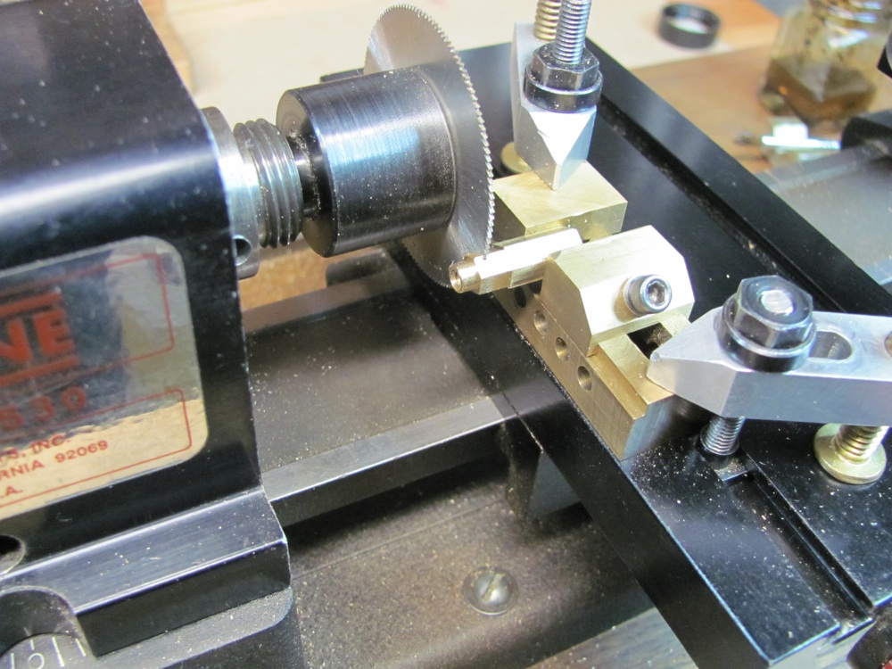 Photo 2 shows a parting off operation with a slitting saw for a #6-32 7/32” hex head shoulder nut for a restoration project. I’ve been using this vise for about 10 years now and I’m quite satisfied with its performance.