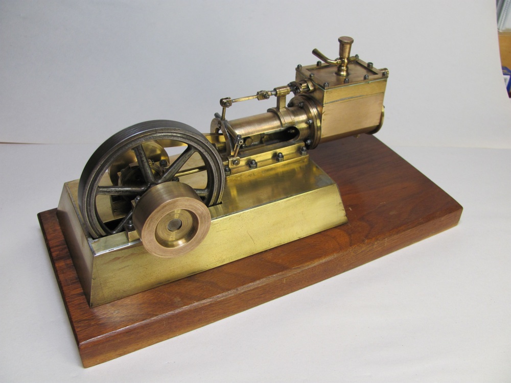
This engine might have been built as a technical school machining project since the bottom includes the builders name and the start (June 1935) and finish (December 1936) dates with draftsman-like penmanship. As received by me in 2007 the engine was cosmetically in very good shape although the clear lacquer coating over some of the parts had been worn off in flat areas, most likely due to repeated polishing. This resulted in these flat areas being tarnished whereas the areas not worn down had a reasonably clean brass look.
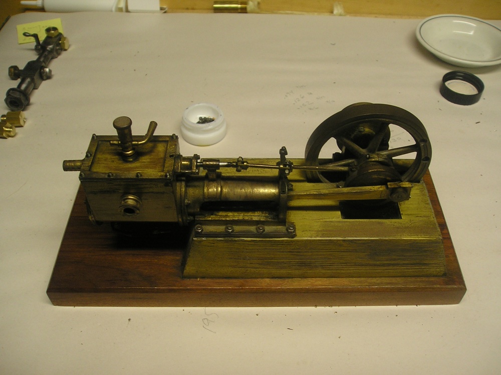
I was impressed with the visual presence of this engine and with its age (about 75 years old) so I decided that I needed to get it running on low pressure compressed air (5 psi max). The local show where I exhibit each year, Old Fashioned Yankee Steam-up in West Greenwich, Rhode Island has a compressed air table for small engines and for the last few years has provided air at 5 psi or less. Before even applying compressed air to this model in my shop I knew that some work was required as the motion of the engine had a significant amount of friction. Before describing the restoration process some description of the model is in order. The cylinder is 1.064” (2.703 mm) inside diameter and the piston stroke is 0.52” (13.2 mm). The flywheel is a 6 spoke steel casting of 3.26” diameter by 0.40” wide. The auxiliary disk is 1.48” diameter by 0.64” wide and may have been for a belt drive. The base is a nice piece of walnut about 10.6” by 4.75”. Also included on the engine are an oiler with valve on the top of the valve chest and two cylinder drain cocks. All fasteners are SAE standards; 0-80, 2-56, 3-48, 5-40, 8- 32, 10-24 and 3/16-24 for the oiler. The use of threaded studs and nuts adds a more authentic look than regular screws.
It was time to see about getting the Hoag engine running again. As it turned out, this took careful attention to the three R’s of engine model restoration; Reducing friction, Reducing air leaks, and Reducing lost motion. First, four sources of significant friction were eventually identified: the valve stem, the D-valve itself, the piston rings, and the cross head. During various stages of assembly / subassembly I acquired a ‘feel’ for the amount of friction in various moving parts. The valve stem ran through the guide on the cross head slide and showed more friction than I thought appropriate. I tried ‘tweaking’ the tightness of the six inner head bolts to improve alignment but this didn’t help. It looked like the valve stem guide was slightly out of true with the mating hole on the cylinder head so I used a 1/8” reamer (with some trepidation) to try and align the two. This worked well and friction was definitely reduced.
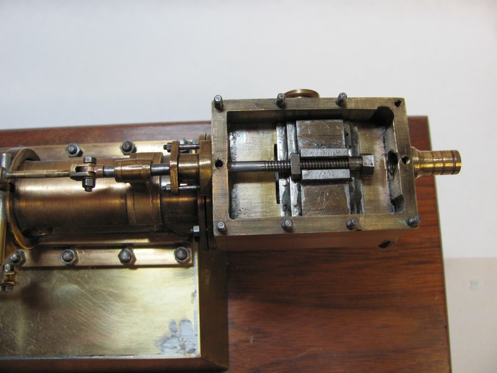
The second tune-up involved the valve itself which is shown in photo 2. As the valve sits on top of the valve face, gravity holds it in place until air pressure is present. I didn’t like the appearance of either of the faces; I polished the valve surface on a flat steel plate with 600 grit emery paper. The valve face opening inside the steam chest required a little ingenuity. I used a short piece of U-channel and a scrap of brass bar (shown in the top right of photo 3) to create a form for guiding the emery paper and I very carefully did some polishing while maintaining the U-channel flush with the valve face. This polishing of the valve and valve face should also help with reducing air leakage between ports. At this point I was quite satisfied with the valve motion.
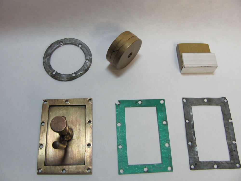
It was time to tackle the piston with its expanding brass piston ring, which is shown in the top center of photo 3. When installing the piston into the cylinder things went smoothly until the piston ring went in, at which point there was that friction thing again. Attempts at removing the piston ring were unsuccessful so a new piston was fabricated. I carefully measured the length between the inner face of the original piston to the end of the piston rod to make sure that I replicated this dimension in the replacement. The new piston was turned to 0.0005” smaller diameter than the cylinder and two small oil grooves were added. I also added two holes in the outer face of piston to allow tightening with a pin wrench I built for a previous restoration.
Things were proceeding well, but there was still some persistent friction in the piston/cross head assembly which I believed was due to the crosshead rubbing on the guide. Once again I tried ‘tweaking’ the six head bolts that held the cross head guide but to no avail. I decided that drastic measures were needed and disassembled the engine to the point where I could hold the piston rod in a collet in my lathe and take a few thousandths off the diameter of the cross head. After one more iteration to remove an additional 0.002 inch from the diameter and the cross head was moving much more smoothly.
The next step was to fully assemble the engine and see how it ran. No luck! Even at 10 psi the piston and crank would only make partial movements and I didn’t want to try higher pressure just yet as I heard hissing noises. As an aside, a few years ago I machined and assembled at Stuart 10V castings set which ran just fine for years on low pressure compressed air. Later on I built a small steam boiler and connected it to the 10V and was amazed at all the little steam leaks that I had never noticed when running on air. Judicious tightening of joints and packing seals solved the 10V steam leakage problem which previously had been invisible.
For the Hoag engine I tried repacking the valve stem and piston rod seals and checked for tightness of the cylinder heads and valve chest cover. The outer cylinder head did not have a gasket and seemed tight enough. The inner cylinder head gasket was a thin sheet of lead and I decided that rather than try and flatten or replace it I would leave it out and rely on the machined surfaces to form a seal. The valve chest cover and its gasket turned out to be the major culprit. The cover itself was quite thin (0.013”) but had a reinforced rim for a total thickness of 0.066”. The cover screws were on 5/8” centers which didn’t provide sufficient uniformity for sealing the cover. In addition, like the inner head, the cover was sealed with a lead gasket.
At that point I noticed that the cover itself was somewhat warped. I applied careful pressure to the edges of the valve cover between two pieces of wood in the arbor press to flatten at appropriate locations, checking frequently with a straight edge and backlighting. I wasn’t enamored with the lead gasket so I cut out a new one. My method for making gaskets for miniature steam engines starts with oil and heat resistant 1/64” gasket material from McMaster-Carr. I carefully draw out the pattern on the gasket and punch out the holes. For custom holes, make a punch from ¼” drill rod by first drilling a hole about 0.010” smaller diameter to about 0.2” deep. Turn the outside to about 0.010” oversize and shape the end of the punch to a knife edge with the center at the desired final diameter of the hole. If you’re only punching a few holes then the punch can be used as is, but if many holes are required then it would be prudent to harden and grind the cutting edge. Then it’s a matter of cutting out the internal and outer dimensions of the gasket with a sharp knife.
Photo 3 shows the original lead gaskets along with the new valve chest cover gasket. While I was at this I decided to do a better job at setting up the valve timing. Because it seems like this engine had very little or no operating time I didn’t expect to find much lost motion. I removed the valve chest cover once more and was surprised to see how much dead time there was between in and out strokes of the valve stem. After some repeated tinkering I determined that one of the valve linkage connections was not fully engaged. This link includes a short rod in a tube. The end of the rod has a square section that seats into the vertical pivot arm the drives the valve rod. This horizontal rod had a shoulder on the outer portion that was preventing it from fully seating into the tube. After filing this rod down the fit was much tighter and the amount of lost motion was barely perceptible. At this point I did some fine tuning of the valve location to ensure balanced opening in both directions. Photo 2 shows the valve at one extreme of motion along with the adjusting screws for equalizing the valve opening in each direction.

During the process of restoration, I used 0000 steel wool and then brass polish to remove the residual lacquer finish and give the engine an overall uniform look. It was time for another test run of my rebuilt Hoag engine which is shown in photo 4. I applied new lubricant here and there (I prefer 10 weight machine oil for these small engines as motor oil is not as refined and dries with a residue). The engine started running fine on about 5 psi air and after a few minutes I could gradually reduce the pressure as the engine ran in. It was ‘mission accomplished!’ as I now have the Hoag engine running on only 2 psi and it’s ready for show time at next year’s Yankee Steam-Up. Look for it if you happen to be there.